Method and system for stably supplying air with low energy consumption

A low-energy-consumption and stable technology, used in combustion methods, non-flammable liquid/gas transportation, indirect carbon dioxide emission reduction, etc., can solve the problems of increased energy consumption, fluctuating gas consumption, and high energy consumption of devices, and achieves lower liquefaction costs, The effect of reducing comprehensive energy consumption and air separation energy consumption

Active Publication Date: 2019-02-01
湖北和远气体股份有限公司
View PDF3 Cites 0 Cited by
  • Summary
  • Abstract
  • Description
  • Claims
  • Application Information

AI Technical Summary

Problems solved by technology

[0004] Based on such gas fluctuations, the existing solutions mainly include the following types. One is to adjust the entire set of air separation plant to make the plant adapt to the new working conditions. However, the air separation plant designs a complete set of equipment, including compressors, Purifiers, expanders, and rectification towers need to adjust the entire process once the gas consumption conditions change, which will be extremely complicated, especially the rectification tower, which is difficult to adjust, and the air separation unit is The design working condition has the lowest energy consumption, and the energy consumption will increase after the working condition changes
Another solution is to design the oxygen output as the average oxygen consumption. When the oxygen consumption is lower than the average consumption, the excess consumption will be liquefied into liquid oxygen. When the oxygen consumption is higher than the average consumption, the liquefied liquid oxygen supply will be used to supplement The part above the average amount; the defect of this scheme is that the energy consumption of the device is high, because the production cost of liquid oxygen must be higher than the production of gaseous oxygen in any way; the defect is that the production of liquid oxygen and not There are two working states for producing liquid oxygen air separation, and the demand for cooling capacity is different. When producing liquid oxygen, the cooling capacity demand of the system is greater, so it is also necessary to adjust the air separation unit. Although the adjustment method is simpler than the previous one, it is also It will make the operation complicated, the air separation unit deviates from the stable design value, and the energy consumption is high
[0005] Another solution is to set the air separation design oxygen production rate as the minimum gas consumption, and then use purchased liquid oxygen to supplement the oxygen consumption when the gas consumption is greater than the design quantity. The defect of this solution is that the purchased liquid oxygen contains liquid Oxygen production cost and transportation cost make its cost higher
[0006] In addition, when the air separation unit produces oxygen, nitrogen is generally produced at the same time. However, customers who use oxygen often use little or no nitrogen. This makes the nitrogen produced by the air separation unit use only a small part for purifier regeneration or its own Except for instrument gas, most of the nitrogen is emptied for nothing; of course, there is a solution to liquefy this part of nitrogen (called external liquefaction) and then export it, but the investment in external liquefaction is high and the cost of nitrogen liquefaction is high, so there is no market competitiveness
[0007] Another conventional idea is to liquefy the vented nitrogen through the heat exchanger with supplementary liquid oxygen, which can reduce the cost of nitrogen liquefaction. However, the temperature of liquid oxygen is only about 180°C, while the liquefaction of nitrogen requires a low temperature of about -196°C. , unless the nitrogen is raised to a higher pressure, but such liquid nitrogen is easy to vaporize in the low-temperature storage tank due to the low self-contained cooling capacity, and it is not easy for general customers to accept it, and the market application is not good, so it is simply replaced by It is also difficult to liquefy nitrogen with a heater

Method used


Image

  • Method and system for stably supplying air with low energy consumption
  • Method and system for stably supplying air with low energy consumption

Examples


Embodiment Construction

[0035] In order to make the object, technical solution and advantages of the present invention clearer, the present invention will be further described in detail below in conjunction with the accompanying drawings and embodiments. It should be understood that the specific embodiments described here are only used to explain the present invention, not to limit the present invention.

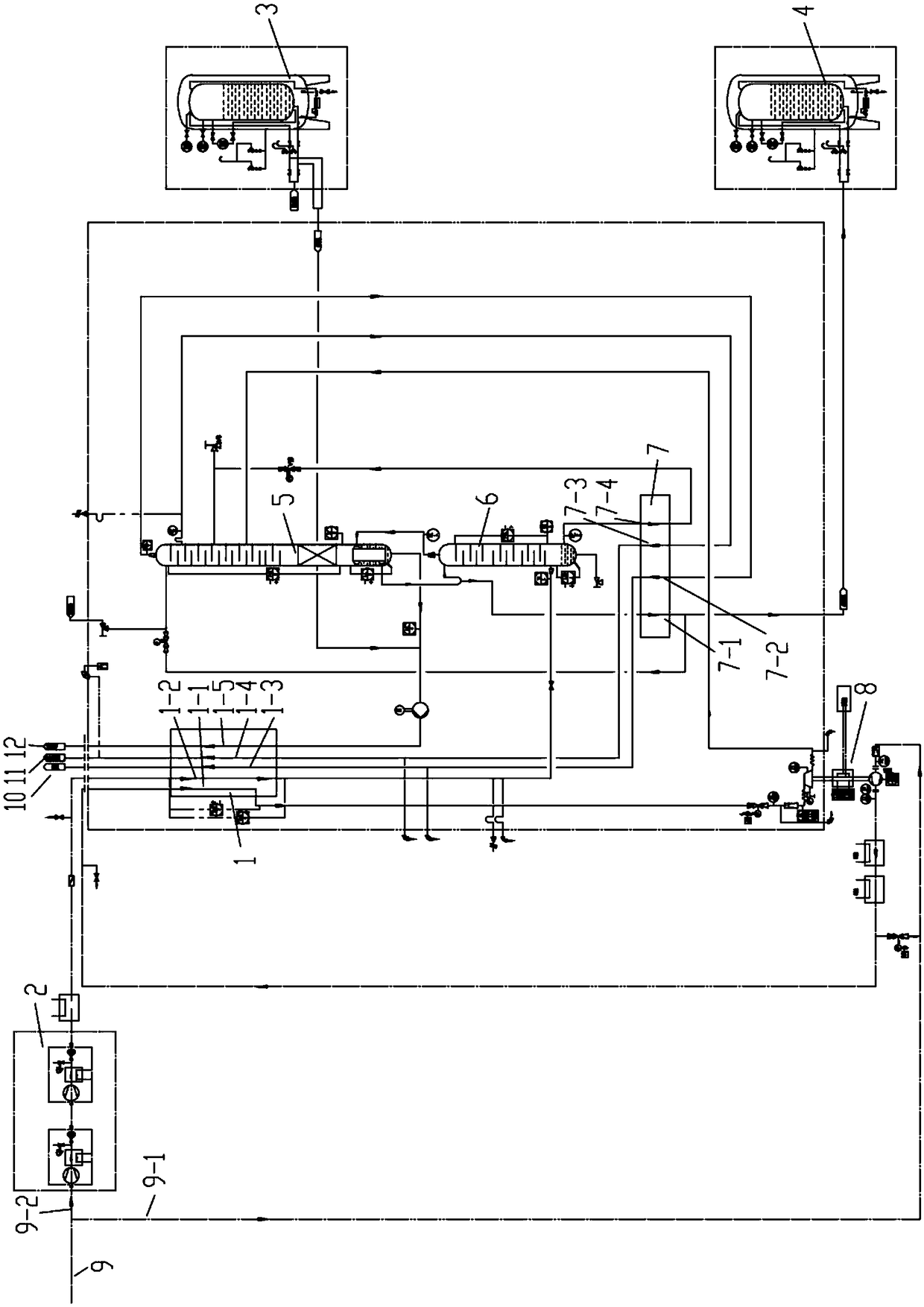
[0036] Such as figure 1 As shown, a method of stable air supply with low energy consumption is obtained by compressing, cooling, purifying, removing water and carbon dioxide to obtain the air to be supplied, and dividing the air to be supplied into two parts to obtain the first A to-be-supplied gas stream and a second to-be-supplied gas stream comprising:

[0037] providing a main heat exchanger 1 with at least five separate fluid circuits, so that the first fluid circuit 1-1 of the main heat exchanger 1 is supplied with a first gas flow to be supplied, the main heat exchanger 1 The second fluid ...


PUM


Abstract

The invention relates to a method and system for stably supplying air with low energy consumption. According to the method, at least part of each of first heat exchange airflow, second heat exchange airflow and third heat exchange airflow is treated to obtain first airflow to be supplied and second airflow to be supplied. The system comprises a piston air booster, an efficient postcooler, a booster expansion turbine, a main heat exchanger with five separated fluid loops, an upper rectifying tower body, a lower rectifying tower body, a subcooler with four separated fluid pipes, a low-temperature liquid nitrogen and a low-temperature liquid nitrogen. Originally-wasted nitrogen generated by air separation is liquefied, the liquefaction cost of nitrogen is reduced as the cooling capacity of liquid nitrogen is fully utilized, benefits generated by the liquid nitrogen basically offset the cost increased by use of the liquid nitrogen, and the overall energy consumption is reduced on the whole.

Description

technical field [0001] The invention relates to the technical field of air separation, in particular to a method and system for stably supplying air with low energy consumption. Background technique [0002] Oxygen is widely used in industry. In many industries (such as electric arc furnace steelmaking), the amount of oxygen used fluctuates greatly. Some industries rely on electricity to control the production volume at night and the production volume during the day. The characteristic of low oxygen content. [0003] Generally speaking, these industries use a large amount of oxygen on average, so many of them use low-temperature air separation units (hereinafter referred to as air separation units) to supply oxygen. [0004] Based on such gas fluctuations, the existing solutions mainly include the following types. One is to adjust the entire set of air separation plant to make the plant adapt to the new working conditions. However, the air separation plant designs a complet...

Claims


Application Information

Patent Timeline
IPC IPC(8): F23L7/00F25J3/04
CPCF23L7/007F25J3/04024F25J3/04109F25J3/0409F25J3/04254F25J3/0426F25J3/04303F25J3/04412F25J2210/50Y02E20/34
Inventor 杜鹏举杨涛杜大艳袁有录
Owner 湖北和远气体股份有限公司
Why Eureka
Try Eureka