Compact differential interferometry imaging spectrograph and imaging method thereof

An imaging spectrometer and differential interferometry technology, applied in the direction of phase influence characteristic measurement, etc., can solve problems that have not been clearly raised, and achieve the effect of light weight, compact structure, and small volume

Pending Publication Date: 2019-02-12
XI'AN INST OF OPTICS & FINE MECHANICS - CHINESE ACAD OF SCI
View PDF0 Cites 3 Cited by
  • Summary
  • Abstract
  • Description
  • Claims
  • Application Information

AI Technical Summary

Problems solved by technology

[0003] All of the above use the real fringe Doppler asymmetric space heterodyne interferometer to detect the space-borne upper atmospheric wind field, which can only realize the detection of atmospheric wind speed. Under certain circumstances, it is necessary to obtain more information about the atmospheric wind field, such as atmospheric composition information, but none of the above papers explicitly proposed that the real fringe Doppler asymmetric spatial heterodyne interferometer has other functions besides detecting atmospheric wind speed

Method used


Image

  • Compact differential interferometry imaging spectrograph and imaging method thereof
  • Compact differential interferometry imaging spectrograph and imaging method thereof
  • Compact differential interferometry imaging spectrograph and imaging method thereof

Examples


Embodiment Construction

[0048] The present invention will be further described below in conjunction with the accompanying drawings.

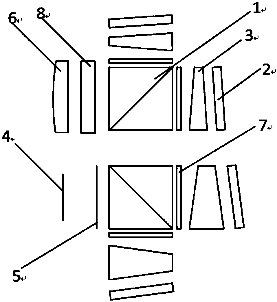
[0049] From figure 1 It can be seen that the system of the present invention includes an interferometer entrance pupil, a telescopic objective lens 6, a filter 8, two sets of interference structures of a high dispersion module and a low dispersion module, an analyzer 5 and a detector 4 array. The high dispersion module and the low dispersion module both include blazed grating 2 components, λ / 4 wave plate 7, field-of-view prism 3 and core component polarization beam splitter prism 1.

[0050] Polarizing beam splitter 1: mainly splits natural light into S polarized light and P polarized light, transmits P polarized light, and reflects S polarized light.

[0051] The blazed grating 2 components are divided into two groups: the grating density of one group is D 1 Used in the low dispersion module, another set of gratings has a line density of D 2 Use in high dispersion...


PUM


Abstract

The invention relates to a compact differential interferometry imaging spectrograph and an imaging method thereof. The spectrograph comprises a telescoping system, a filter, a low-chromatic-dispersionmodule, a high-chromatic-dispersion module, a polarization analyzer and a detector, wherein the telescoping system, the filter, the low-chromatic-dispersion module, the high-chromatic-dispersion module, the polarization analyzer and the detector are arranged along a light path; the low-chromatic-dispersion module and the high-chromatic-dispersion module independently comprise a polarizing beam splitting prism, a 1/4 wave plate, a view field expanding prism, a blazed grating, a 1/4 wave plate, a view field expanding prism and a blazed grating, wherein the 1/4 wave plate, the view field expanding prism and the blazed grating are arranged in a transmission light path of the polarizing beam splitting prism in sequence, and the 1/4 wave plate, the view field expanding prism and the blazed grating are arranged in the reflecting light path of the polarizing beam splitting prism in sequence; the telescoping system is used for collecting the spectral radiance of an observation target; the filter is used for filtering the collected spectral radiance of the observation target; the low-chromatic-dispersion module is used for carrying out light splitting on filtered rays; the high-chromatic-dispersion module is used for gathering and emitting the rays; the polarization analyzer is used for carrying out beam combination on emergent light; and the detector is used for receiving an interference image emitted from the polarization analyzer and carrying out imaging on the spectral radiance collected by the telescoping system. The spectrograph is applied to atmospheric composition detection,and atmospheric compositions can be obtained through obtained spectrum information.

Description

technical field [0001] The invention relates to a compact differential interference imaging spectrometer and an imaging method thereof. Background technique [0002] In 2013, John M.Harlander proposed the concept of a real fringe Doppler asymmetric space heterodyne interferometer (HARLANDER J M,ENGLERTC R.Design of a real-fringe DASH interferometer for observations of thermospheric winds from a small satellite[C].FourierTransform Spectroscopy.Optical Society of America,2013:FW1D.2.), and based on the oxygen atom red line (O[ 1 D]630nm) for spaceborne upper atmospheric wind field detection, and give the parameters of the design system and a specific simulation model. In 2015, Xi'an Institute of Optics and Fine Mechanics, Chinese Academy of Sciences explained the concept and basic principles of real fringe Doppler asymmetric spatial heterodyne interferometer in detail, (FEI Xiao-yun, FENG Yu-tao, BAI Qing-lan, et al. al..Real-fringe DASH interferometer for upper atmospheric ...

Claims


Application Information

Patent Timeline
Patent Type & Authority Applications(China)
IPC IPC(8): G01N21/45
CPCG01N21/45
Inventor 冯玉涛尹诗郝雄波李娟傅頔白清兰孙剑胡炳樑刘学斌
Owner XI'AN INST OF OPTICS & FINE MECHANICS - CHINESE ACAD OF SCI
Why Eureka
Try Eureka