Calibrating a catadioptric camera by using the property of an infinitely distant point with respect to a circular pole line

An infinity point, catadioptric technology, applied in the field of computer vision, can solve the problem of complex circle point selection

Inactive Publication Date: 2019-02-12
YUNNAN UNIV
View PDF3 Cites 7 Cited by
  • Summary
  • Abstract
  • Description
  • Claims
  • Application Information

AI Technical Summary

Problems solved by technology

However, the selection of the image of the ring point in this document is more complicated

Method used


Image

  • Calibrating a catadioptric camera by using the property of an infinitely distant point with respect to a circular pole line
  • Calibrating a catadioptric camera by using the property of an infinitely distant point with respect to a circular pole line
  • Calibrating a catadioptric camera by using the property of an infinitely distant point with respect to a circular pole line

Examples


Embodiment

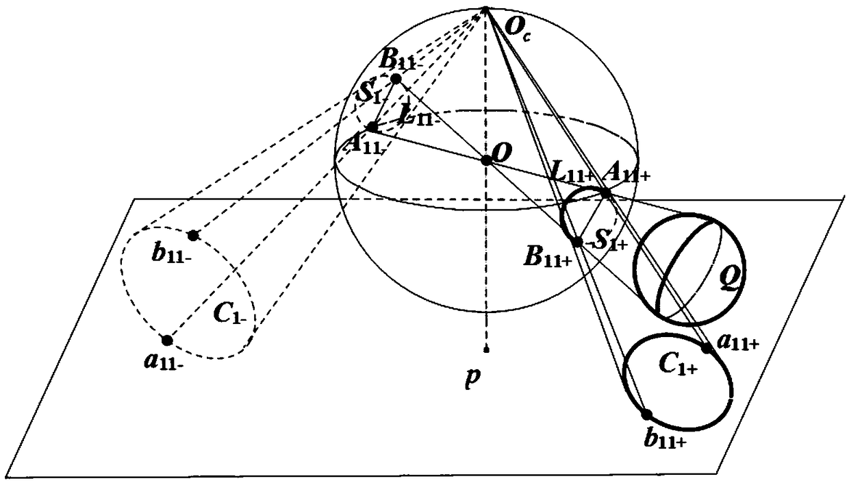
[0058] The invention proposes a method for linearly determining internal parameters of a parabolic catadioptric camera by using a sphere in space as a target. The experimental template structural schematic diagram that the present invention adopts is as figure 1 shown. The implementation of the present invention will be described in more detail with an example below.

[0059] The experimental template used in the calibration of parabolic catadioptric cameras based on spheres in space is a sphere in space, such as figure 1 As shown, the ball is Q. Utilize the method among the present invention to carry out calibration for the parabolic catadioptric camera that is used for experiment, concrete steps are as follows:

[0060] 1. Fit image boundary and target curve equation

[0061] The image size used in the present invention is 1300×1200. Use the parabolic catadioptric camera to shoot 3 experimental images of the target, read the images, use the Edge function in Matlab to ex...


PUM


Abstract

A method for calibrating a catadioptric camera by using the property of an infinitely distant point with respect to a circular pole line is characterized in that a ball in space is used as a target. The method comprises the following steps of firstly extracting edge points of a target image and edge points of a mirror contour projection of one image from three images respectively; secondly, according to the relation between the image point and its extension point, obtaining the extension point, and then fitting the extension spherical image of the spherical image; taking two different points on the spherical image and obtaining the opposite extension points of the two points; according to the definition of topological points and the properties of circles, using the two sets of topologicalpoints to provide a vanishing point; taking two dissimilar points from the spherical image, and obtaining two vanishing points. Wherein the straight line of the two vanishing points is the vanishing line; finally, obtaining the camera intrinsic parameters by using the constraint of the orthogonal vanishing point to the absolute conic image.

Description

technical field [0001] The invention belongs to the field of computer vision and relates to a method for solving the internal parameters of a parabolic catadioptric camera by using the properties of a ball and an infinite point in space with respect to a circular epipolar line. Background technique [0002] The central task of computer vision is to understand images, and its ultimate goal is to enable computers to have the ability to recognize three-dimensional environmental information through two-dimensional images. This ability will not only enable the machine to perceive the geometric information of objects in a three-dimensional environment including shape, posture, motion, etc., but also describe, store, recognize and understand them. Camera calibration is to determine the mapping relationship from a three-dimensional space point to its two-dimensional image point, which is an essential step in many computer vision applications. In order to determine this mapping proc...

Claims


Application Information

Patent Timeline
IPC IPC(8): G06T7/80
CPCG06T7/80
Inventor 赵越李远珍
Owner YUNNAN UNIV
Why Eureka
Try Eureka