A manufacturing process of a girder for thermal power plant construction
A thermal power plant and manufacturing process technology, applied in the direction of manufacturing tools, auxiliary molding equipment, ceramic molding machines, etc., can solve the problems of poor debris collection effect, high maintenance cost, poor adjustability, etc., and achieve good debris collection effect , Low maintenance cost, the effect of reducing maintenance cost
- Summary
- Abstract
- Description
- Claims
- Application Information
AI Technical Summary
Problems solved by technology
Method used
Image

Examples
Embodiment 1
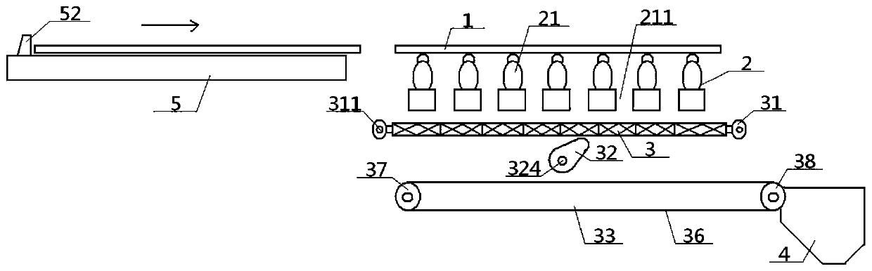
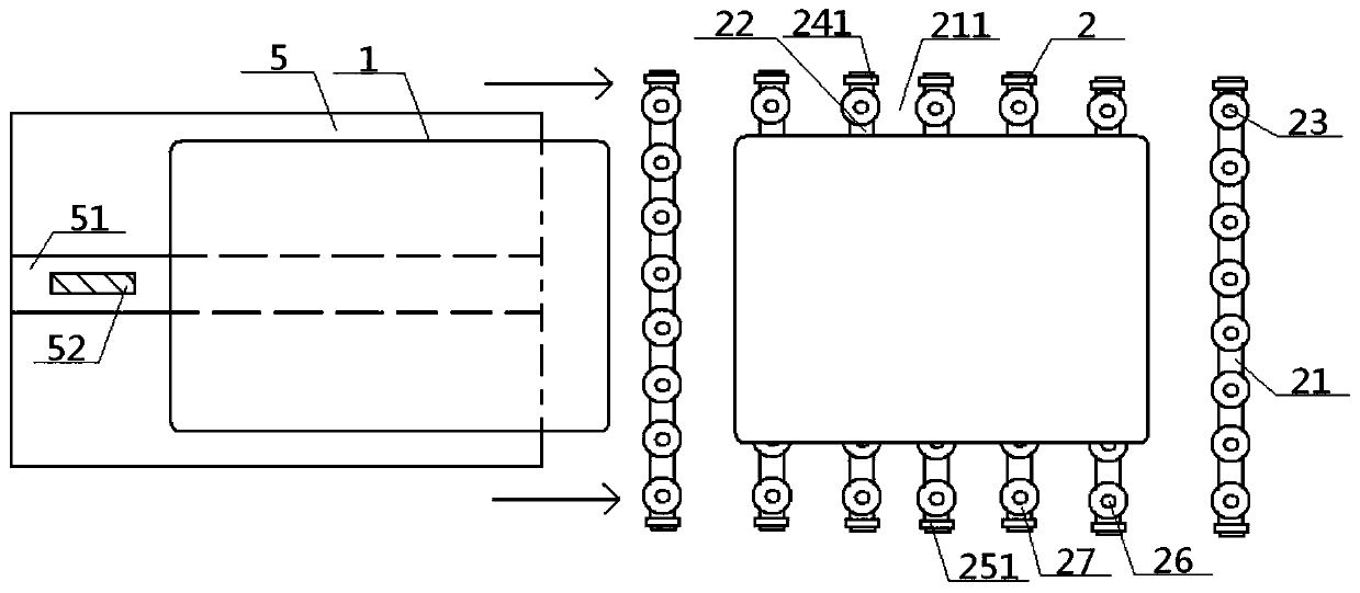
[0061] see Figure 1 to Figure 12 , a manufacturing process of a girder for construction of a thermal power plant, the manufacturing process includes a plate cutting step, a welding step, a straightening step, a grinding step and a painting step carried out in sequence, and the plate cutting step refers to placing a metal plate 1 on a cutting unit 2 is cut to obtain plate parts, the welding step refers to welding the aforementioned plate parts to obtain the girder blank, and the rectification step refers to mechanically straightening or flame straightening the girder blank to obtain For the straightening piece, the grinding and painting steps refer to sequentially grinding and painting the straightening piece to obtain the product; in the plate cutting step, the cutting of the metal plate 1 on the cutting unit 2 refers to: first The metal plate 1 to be processed is transported to the plate feeding unit 5, and then the plate feeding pusher 52 is driven to move horizontally alon...
Embodiment 2
[0064] Basic content is the same as embodiment 1, the difference is:
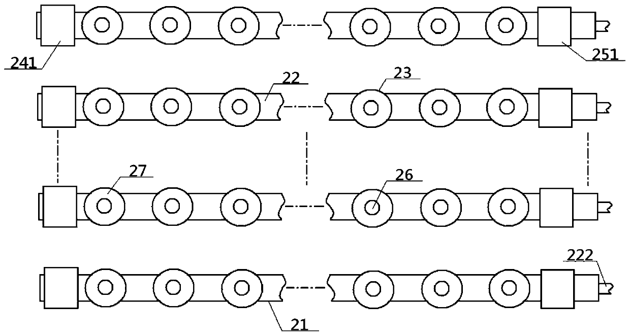
[0065] The elongated base 22 is a hollow structure, and the inside of the elongated base 22 is provided with a coaxial elongated cavity 221, one end of the elongated cavity 221 is flush with the end face of the elongated base 22, and the elongated cavity The other end of 221 is connected with the intake pipe head 222; the plastic ball seat 27 includes a spherical portion 28 and a fixed portion 29, the side of the spherical portion 28 is a spherical structure, and the side of the spherical portion 28 is provided with a plurality of Air vent 272, the top of spherical portion 28 is connected with the bottom of metal ball 26, the bottom of spherical portion 28 is connected with the top of fixed portion 29, and the bottom of fixed portion 29 passes through the top surface of elongated substrate 22 In contact with the strip cavity 221, the inside of the spherical portion 28 is provided with a spherical cavity 281...
Embodiment 3
[0067] Basic content is the same as embodiment 1, the difference is:
[0068] The miscellaneous device 33 includes a miscellaneous crawler belt 36, a left miscellaneous roller 37 and a right miscellaneous roller 38, and the two ends of the miscellaneous crawler belt 36 are respectively wrapped around the rollers of the left miscellaneous roller 37 and the right miscellaneous roller 38. On the surface, a plurality of miscellaneous partition strips 361 are uniformly arranged on the outer surface of the miscellaneous crawler 36, and the bottom of the miscellaneous partition strip 361 is vertically connected with the outer surface of the miscellaneous crawler 36, and the adjacent miscellaneous partition strips 361 are parallel to each other, and the adjacent miscellaneous partition strips 361 and the miscellaneous track 36 between them constitute a miscellaneous box 362 .
PUM
 Abstract
Description
Claims
Application Information
 - R&D
- Intellectual Property
- Life Sciences
- Materials
- Tech Scout
- Unparalleled Data Quality
- Higher Quality Content
- 60% Fewer Hallucinations
Browse by: Latest US Patents, China's latest patents, Technical Efficacy Thesaurus, Application Domain, Technology Topic, Popular Technical Reports.
© 2025 PatSnap. All rights reserved.Legal|Privacy policy|Modern Slavery Act Transparency Statement|Sitemap|About US| Contact US: help@patsnap.com