
Steel bending equipment for steel processing

A technology of steel and steel, which is applied in the field of steel bending equipment for steel processing, and can solve problems that affect the bending effect of U-shaped steel, cannot bend steel plates, and affect the quality of U-shaped steel, etc.

Active Publication Date: 2019-02-19
江苏江锻机械科技有限公司
View PDF6 Cites 2 Cited by
  • Summary
  • Abstract
  • Description
  • Claims
  • Application Information

AI Technical Summary

Problems solved by technology

The processing of existing U-shaped steel is through such as the patent No. is CN106825136B a kind of steel plate bending equipment for hardware making, in this patent, through the first extruding device, the second extruding device, the first pushing device, the second pushing device , the mutual cooperation between the motor device and the abutment device can simultaneously bend both sides of the steel plate, and complete the bending operation of U-shaped steel production. The bending efficiency of steel plates, but it is impossible to bend steel plates of different widths and thicknesses, resulting in very low practicability; second, the U-shaped groove depth of U-shaped steel cannot be adjusted according to production needs; third, the steel plate is bending During the process, the force on the bending part of the steel plate cannot be guaranteed, which seriously affects the bending effect of the U-shaped steel, and even affects the quality of the U-shaped steel.

Method used


Image

  • Steel bending equipment for steel processing
  • Steel bending equipment for steel processing
  • Steel bending equipment for steel processing

Examples


Embodiment Construction

[0028] The technical solutions of the present invention will be clearly and completely described below in conjunction with the accompanying drawings. Obviously, the described embodiments are part of the embodiments of the present invention, rather than all of them.

[0029] The components of the embodiments of the present invention generally described and shown in the drawings herein may be arranged and designed in various different configurations. Therefore, the following detailed description of the embodiments of the present invention provided in the accompanying drawings is not intended to limit the scope of the claimed invention, but merely represents selected embodiments of the present invention.

[0030] Based on the embodiments of the present invention, all other embodiments obtained by those of ordinary skill in the art without creative work shall fall within the protection scope of the present invention.

[0031] In the description of the present invention, it should be note...


PUM


Abstract

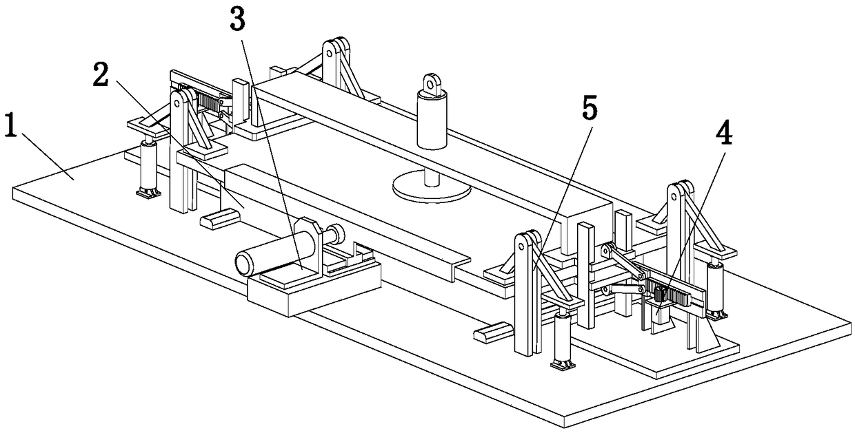
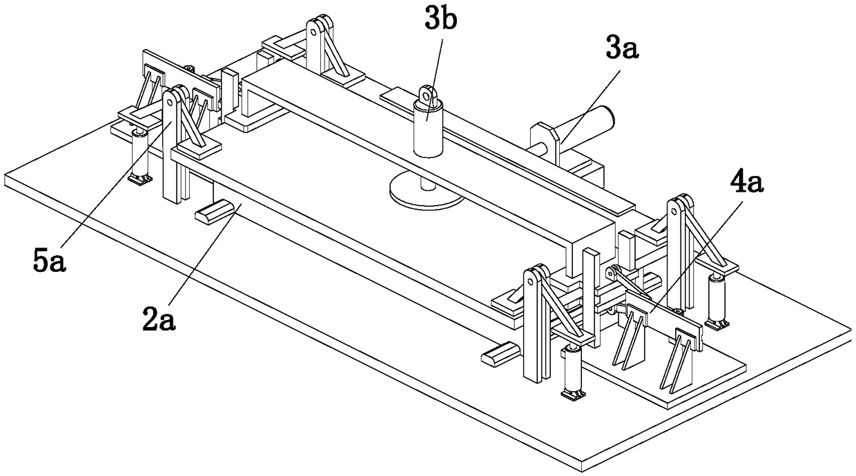
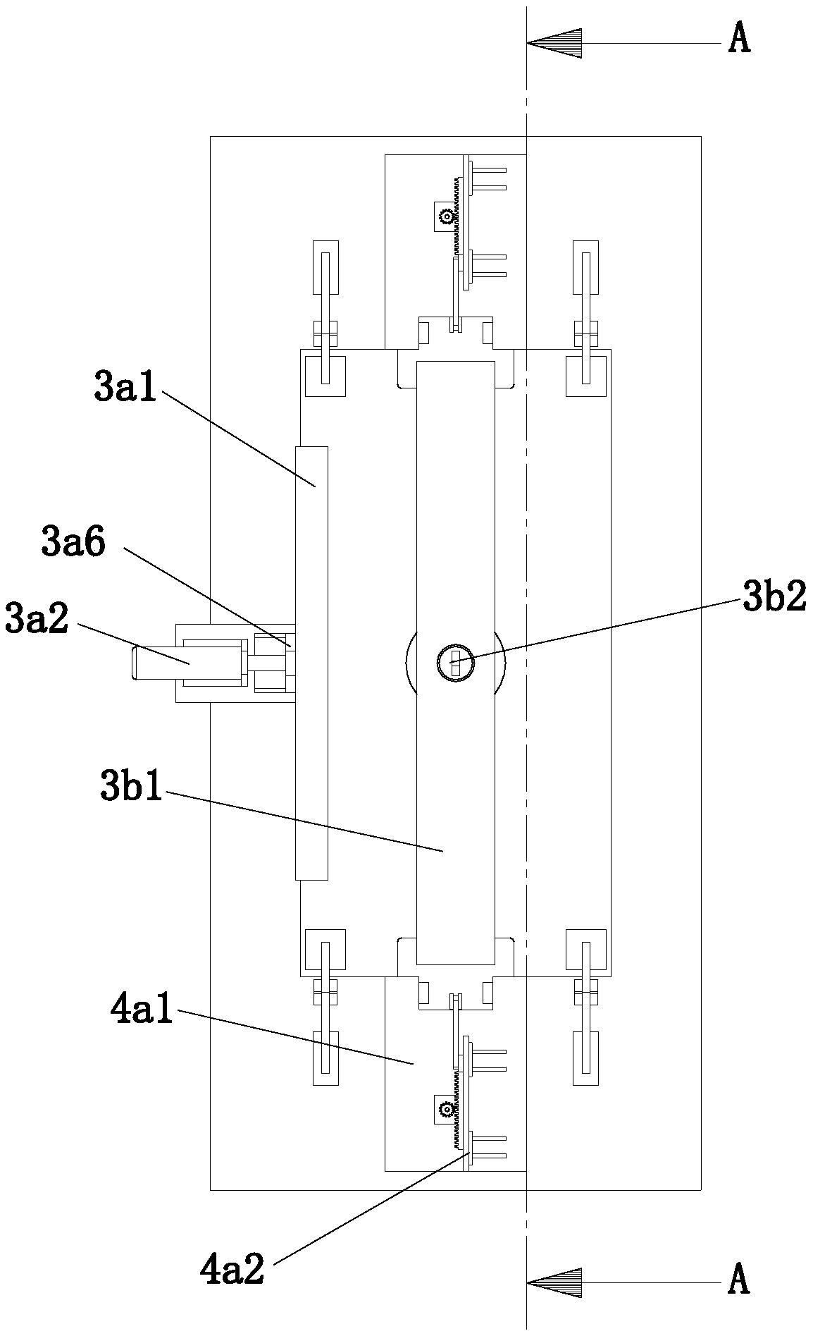
The invention discloses steel bending equipment for steel processing, and belongs to the technical field of steel processing. The steel bending equipment for the steel processing comprises a substrate, a bearing drive mechanism, a limiting mechanism, a positioning mechanism and a bending mechanism, and the bearing drive mechanism, the limiting mechanism, the positioning mechanism and the bending mechanism are all arranged on the top of the substrate. The bearing drive mechanism comprises a support assembly, a linkage assembly and a drive assembly, wherein the two ends of the linkage assembly are fixedly connected with the support assembly and are in transmission connection with the drive assembly; the positioning mechanism comprises two interlocking clamping assemblies; the bending mechanism comprises four downward pressing assemblies which are distributed in a rectangular mode; and the limiting mechanism comprises an adjusting moving assembly and a pressing assembly, the output end ofthe adjusting moving assembly is arranged perpendicular to the length direction of the substrate, and the two ends of the pressing assembly are fixedly and separately connected with the two interlocking clamping assemblies. According to the steel bending equipment for the steel processing, steel plates with different widths and thicknesses can be bent, the practicability is high, and the depth ofa U-shaped groove of U-shaped steel can be adjusted according to production requirements.

Description

Technical field [0001] The invention relates to the technical field of steel processing, in particular to a steel bending equipment for steel processing. Background technique [0002] Steel is an alloy composed of iron and carbon, silicon, manganese, phosphorus, sulfur and a small amount of other elements. Steel is produced from iron ore. In order to improve the performance of steel, the iron element is combined with various small elements to form a special form, so that the metal has higher technical parameters. It is the most important and most important in engineering technology. , The most used metal material. [0003] As a common steel structure in steel, U-shaped steel has the characteristics of high pressure resistance, long support time, easy installation and non-deformation, so it is widely used in construction and industry. The existing U-shaped steel is processed by a steel plate bending equipment for hardware manufacturing such as the patent number CN106825136B. The ...

Claims


Application Information

Patent Timeline
Patent Type & Authority Applications(China)
IPC IPC(8): B21D5/01B21D43/00
CPCB21D5/01B21D43/00
Inventor 董淑翠初丽萍段小宁
Owner 江苏江锻机械科技有限公司
Learn More