A kind of propeller processing technology

A processing technology and propeller technology, applied in the direction of rotating propellers, rotary propellers, etc., can solve the problems of poor fluidity, high melting point of stainless steel, and difficult implementation of stainless steel, and achieve high implementability, overcome difficulties in manufacturing, and high toughness Effect

Inactive Publication Date: 2020-03-31
SANMEN ZHONGLI MACHINERY MFG CO LTD
View PDF6 Cites 0 Cited by
  • Summary
  • Abstract
  • Description
  • Claims
  • Application Information

AI Technical Summary

Problems solved by technology

[0004] However, the manufacture of stainless steel propellers is far more difficult than that of copper alloys. The main difficulties are: 1. The melting point of stainless steel is much higher than that of copper alloys, and its fluidity is poor. It is difficult to directly cast stainless steel propellers; 2. The current processing of copper alloy propellers is average. Mainly cutting and grinding, but it is difficult to implement for stainless steel with high strength and hardness
This leads to the problem that the propeller made of stainless steel is difficult to manufacture

Method used


Image

  • A kind of propeller processing technology
  • A kind of propeller processing technology
  • A kind of propeller processing technology

Examples


Embodiment 1

[0045] A kind of propeller processing technology, comprises the steps:

[0046] Step S1: cutting the stainless steel plate into blade-shaped blanks. The stainless steel plate in this embodiment is 420 stainless steel, and the stainless steel plate is the raw material for manufacturing propeller blades. The cutting can be completed by a laser cutting machine, and the blade blank after cutting is still a plate with uniform thickness.

[0047] Step S2: heating the blade blank to 1100-1300°C. This process is completed by sending the blade blank into the heating furnace, and the blade blank is in a red state after heating.

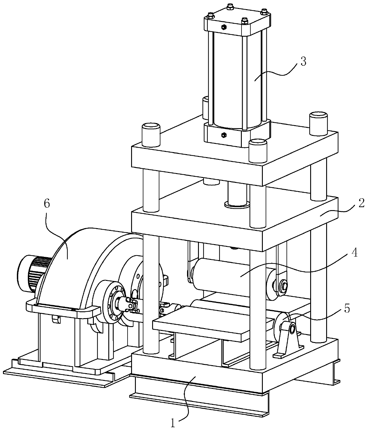
[0048] Step S3: Take the heated blade blank out of the heating furnace, and then press it into a required thickness by a hydraulic press. Step S3 includes Step S31 and Step S32.

[0049] Step S31: Using a hydraulic press to pressurize the board surface of the blade blank to form the required board thickness of the blade gradually changing.

[0050] Such as ...

Embodiment 2

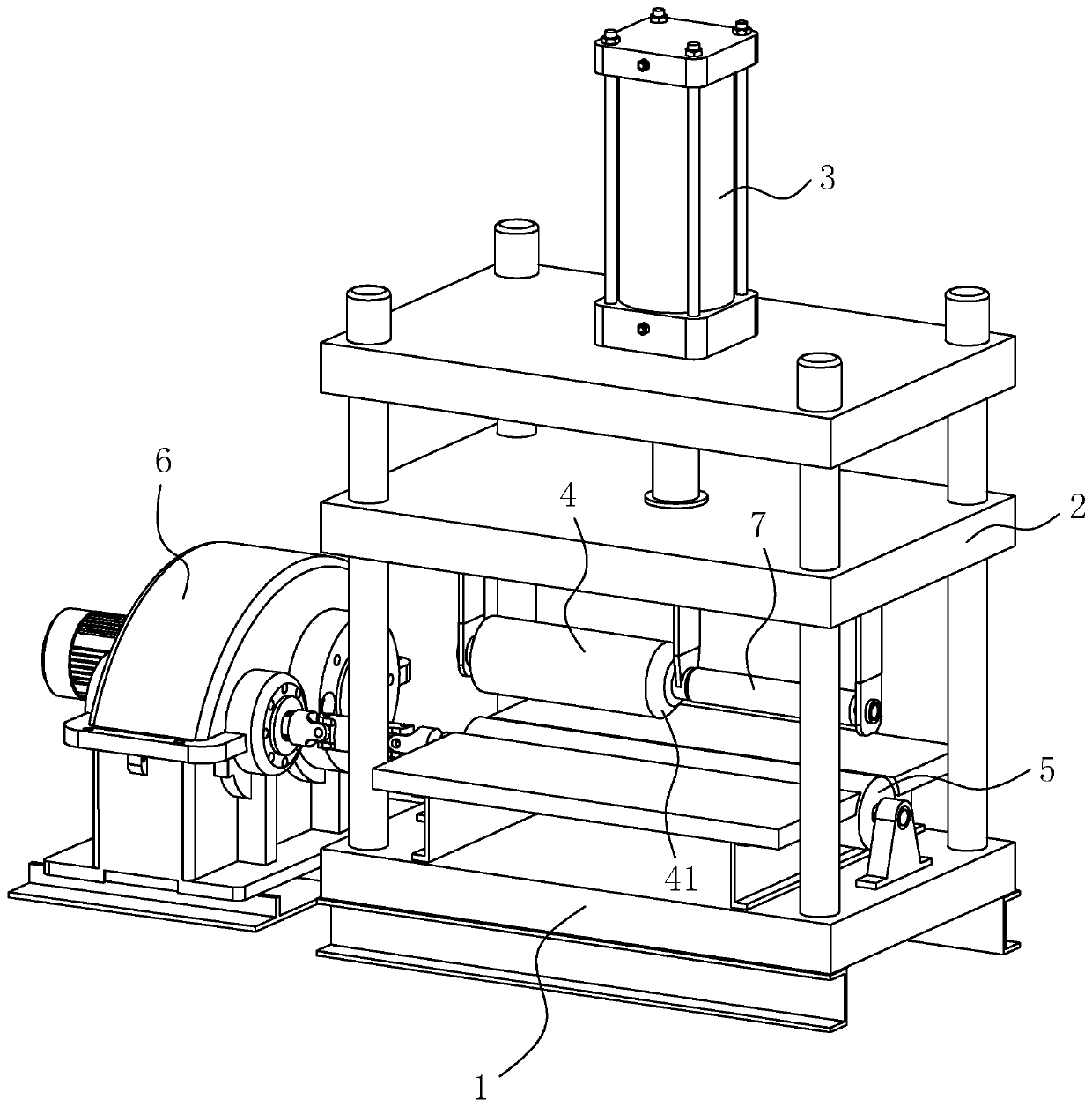
[0069] Such as figure 2 As shown, the difference between Embodiment 2 and Embodiment 1 is that the limit roller 7 is coaxially arranged at the end of the upper pressure roller 4 of the hydraulic press used in step S3, and the limit roller 7 is also rotated and arranged on the pressure plate 2. The axis of rotation of 7 coincides with the axis of rotation of the upper pressure roller 4, the diameter of the limit roller 7 is smaller than that of the upper pressure roller 4, and the upper pressure roller 4 is provided with an inclined secondary pressure surface 41 towards the axial end of the limit roller 7, The auxiliary pressing surface 41 is tapered, and the auxiliary pressing surface 41 is used to shape the edge thickness of the blade gradually;

[0070] When step S31 is executed, the blade is placed under the upper pressing roller 4 for processing. When step S32 is executed, the blade is placed under the limit roller 7 for processing. During processing, the edge of the bla...


PUM


Abstract

The invention discloses a propeller machining process, and relates to the technical field of ships. According to the technical scheme, the process comprises S1, a stainless steel plate is cut into a blade-shaped blank; S2, the blade blank is heated; S3, the heated blade blank is pressed into the blank with a required thickness through a hydraulic press; S4, the appearance size of the blade is cut;S5, after the blade is heated, the blade is placed into a mold with a corresponding shape to be forged; S6, a pre-manufactured stainless steel propeller hub is taken, and the blade is positioned on the propeller hub and is welded to form a propeller whole; S7, the propeller is subjected to heat treatment; S8, machining is carried out on the propeller; and S9, grinding and polishing are conductedon the surface of the propeller. According to the propeller machining process, the feasibility is high, and the problem that the stainless propeller is difficult to produce and manufacture is solved;through rolling, forging and heat treatment processes, the produced propeller is high in strength and toughness.

Description

technical field [0001] The invention relates to the technical field of ships, in particular to a propeller processing technology. Background technique [0002] The propeller is an important part of a ship. With the continuous development of the shipbuilding industry and the increase in size and speed of modern ships, the performance requirements for ship propellers are also getting higher and higher. [0003] For a long time, copper alloys have been mostly used as materials for marine propellers, among which nickel-aluminum bronze is the preferred material. Due to the limited strength and hardness of the propeller made of copper alloy, it is prone to serious deformation or even fracture when it collides with stones and driftwood. With the enlargement of ships and the increase of single-shaft power, it is urgent to develop propeller materials with higher strength. In addition, seawater pollution in harbors and rivers has intensified in recent years, and the corrosion resist...

Claims


Application Information

Patent Timeline
Patent Type & Authority Patents(China)
IPC IPC(8): B23P15/00
CPCB23P15/00B63H1/14
Inventor 王国勤
Owner SANMEN ZHONGLI MACHINERY MFG CO LTD
Why Eureka
Try Eureka