Pulsed abrasive flow polishing device and method

A polishing device and pulse type technology, which is applied in the direction of grinding/polishing equipment, used abrasive processing devices, surface polishing machine tools, etc., can solve problems such as complex equipment and processing accuracy problems

Active Publication Date: 2019-02-19
CHANGCHUN UNIV OF SCI & TECH
View PDF8 Cites 5 Cited by
  • Summary
  • Abstract
  • Description
  • Claims
  • Application Information

AI Technical Summary

Problems solved by technology

[0004] The technical problem of the present invention is to overcome the deficiencies of the existing technology, provide a pulsed abrasive flow polishing device and method, solve the existing processing accuracy problem and the problem of relatively complicated equipment, and realize high-precision, easy-to-operate, green and efficient processing

Method used


Image

  • Pulsed abrasive flow polishing device and method
  • Pulsed abrasive flow polishing device and method
  • Pulsed abrasive flow polishing device and method

Examples


Embodiment 1

[0075] Take the processed workpiece 6 of No. 45 quenched and tempered heat-treated steel as embodiment 1, and its specific implementation method is as follows:

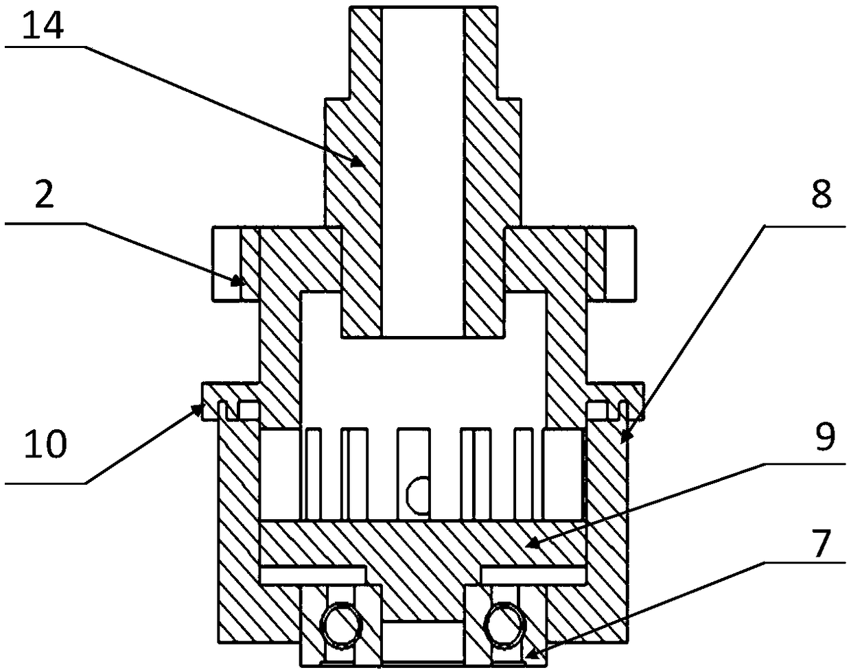
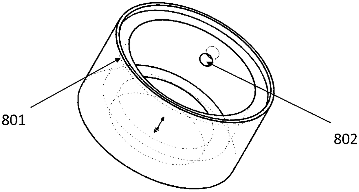
[0076] Step 1: After selecting the stator 8 and the rotor 10 and installing them, adopt the stator 8 and the rotor 10 with a rectangular tooth shape 1002 and a rectangular pressure outlet 802 , and the width of the baffle plate 1003 is larger than the width of the rectangular pressure outlet 802 .

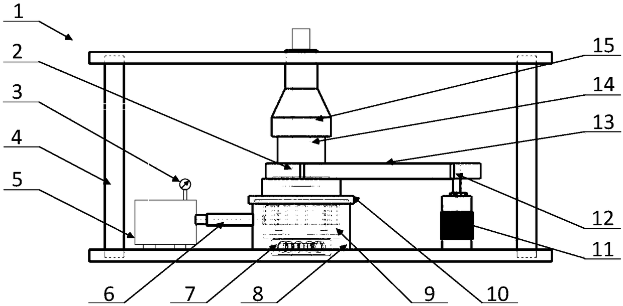
[0077] Step 2: The hydraulic pump 5 is turned on, and the grinding fluid is stably delivered to the inside of the rotor 10 through the hydraulic oil circuit 1, the upper joint 15 and the rotary joint 14, and the stable supply of the specified pressure is realized through the detection of the hydraulic pressure gauge 3.

[0078] Step 3: The baffle plate 1003 of the rotor 10 is opposite to the pressure outlet 802 of the stator 8, thus forming a closed space, the pipeline is disconnected without processing, and the hydraulic p...

Embodiment 2

[0086] Taking the processed workpiece 6 of processing stainless steel as embodiment 2, the specific implementation method is as follows:

[0087] Step 1: After the stator 8 and the rotor 10 are selected and installed, the stator 8 and the rotor 10 adopt the rectangular tooth shape 1002 and the circular pressure outlet 802 or the sine-cosine tooth shape 1002 and the rectangular pressure outlet 802 .

[0088] Step 2: The hydraulic pump 5 is turned on, and the grinding fluid is stably delivered to the inside of the rotor 10 through the hydraulic oil circuit 1, the upper joint 15 and the rotary joint 14, and the stable supply of the specified pressure is realized through the detection of the hydraulic pressure gauge 3.

[0089] Step 3: The baffle plate 1003 of the rotor 10 is opposite to the pressure outlet 802 of the stator 8, thus forming a closed space, the pipeline is disconnected without processing, and the hydraulic pump 5 automatically pumps the grinding fluid when the press...

Embodiment 3

[0097] Take the processed workpiece 6 of industrial pure titanium as embodiment 3, and its specific implementation method is as follows:

[0098] Step 1: After selecting the stator 8 and the rotor 10 and installing them, adopt the stator 8 and the rotor 10 with a rectangular tooth shape 1002 and a rectangular pressure outlet 802 , and the width of the tooth shape 1002 is larger than the width of the pressure outlet 802 .

[0099] Step 2: The hydraulic pump 5 is turned on, and the grinding fluid is stably delivered to the inside of the rotor 10 through the hydraulic oil circuit 1, the upper joint 15 and the rotary joint 14, and the stable supply of the specified pressure is realized through the detection of the hydraulic pressure gauge 3.

[0100] Step 3: The baffle plate 1003 of the rotor 10 is opposite to the pressure outlet 802 of the stator 8, thus forming a closed space, the pipeline is disconnected without processing, and the hydraulic pump 5 automatically pumps the grindi...


PUM

PropertyMeasurementUnit
Hardnessaaaaaaaaaa
Hardnessaaaaaaaaaa
Hardnessaaaaaaaaaa

Abstract

The invention relates to a pulsed abrasive flow polishing device and method, and provides a pulse generating device which can generate four different pressure forms. Different tooth forms and tooth spacings are designed, and different mechanical structures are used for generating stable sinusoidal pressure wave, triangular pressure wave, trapezoidal pressure wave and standard sine-cosine pressurewave, so that the effect of increasing the fluid turbulent kinetic energy is achieved, the uniform machining effect is achieved, additionally, different pressure forms are selected according to different material hardness and high-temperature oxidation effects during machining, the characteristics of different kinds of pressure wave are exerted, and the machining effects of high efficiency and economy are achieved.

Description

technical field [0001] The invention belongs to the field of abrasive flow processing technology and ultra-precision processing, and specifically designs a pulsed abrasive flow polishing device and method. The abrasive flow processing technology is widely used in the fields of automobiles, aerospace and biomedicine. Pulsed abrasive flow belongs to the field of ultra-precision technology processing. Background technique [0002] Abrasive flow polishing is the removal of material produced by friction between abrasive particles near the wall and the wall surface of the workpiece under the action of pressure. Therefore, when only considering the collision between particles and the wall surface and not considering the surface oxidation caused by high temperature, The greater the particle concentration, the more the number of particles, the better the processing effect, and the laminar flow field will make the surface of the workpiece show a certain regularity, which is not allowe...

Claims


Application Information

Patent Timeline
IPC IPC(8): B24C3/32B24C9/00B24B31/116B24B31/12
CPCB24B31/116B24B31/12B24C3/325B24C9/00
Inventor 石岩简永超刘佳倪聪
Owner CHANGCHUN UNIV OF SCI & TECH
Why Eureka
Try Eureka