A pulsed abrasive flow polishing device and method
A polishing device and abrasive flow technology, which can be used in grinding/polishing equipment, used abrasive treatment devices, surface polishing machine tools, etc., and can solve problems such as machining accuracy and complex equipment.
- Summary
- Abstract
- Description
- Claims
- Application Information
AI Technical Summary
Problems solved by technology
Method used
Image
Examples
Embodiment 1
[0075] Take the processed workpiece 6 of No. 45 quenched and tempered heat-treated steel as embodiment 1, and its specific implementation method is as follows:
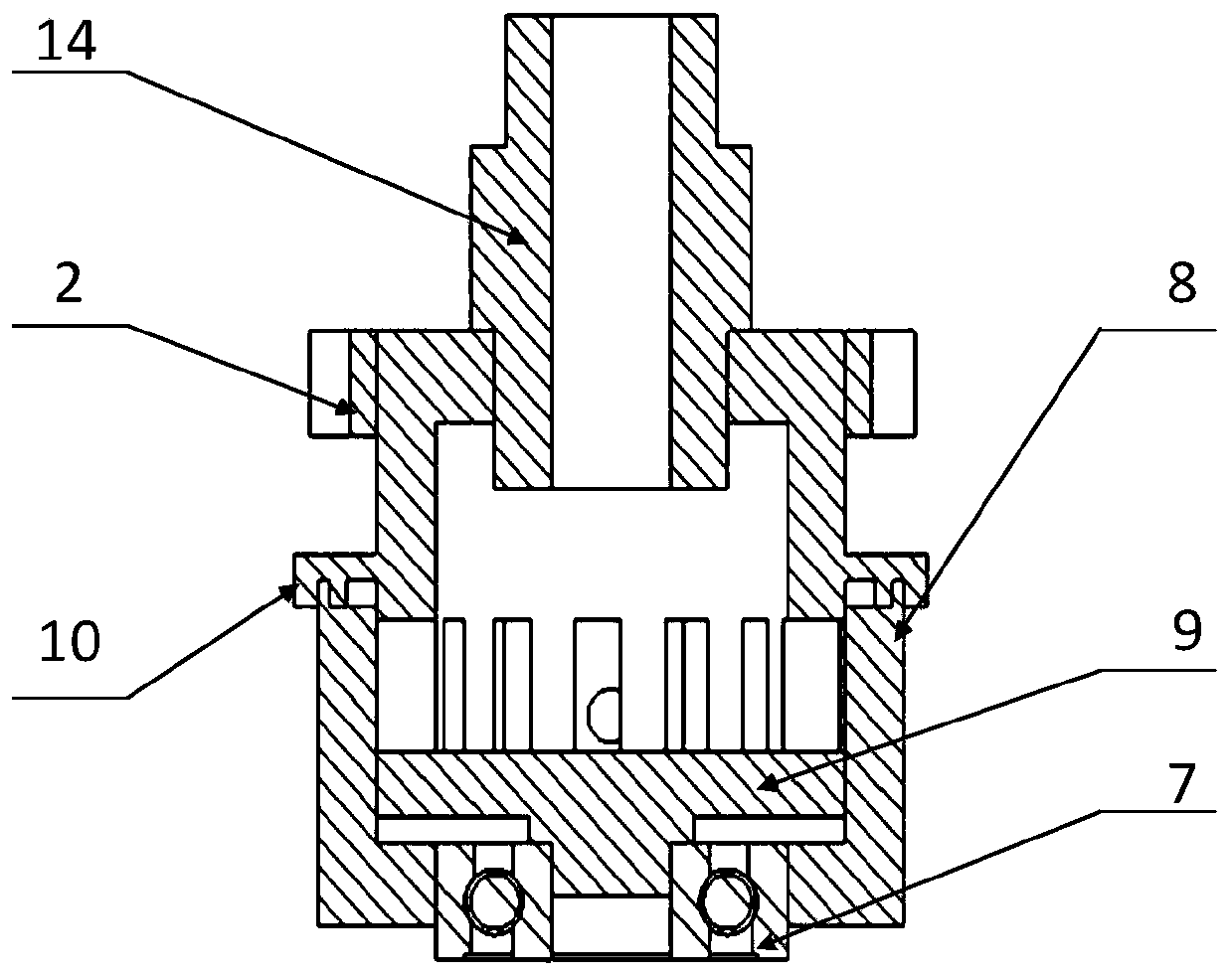
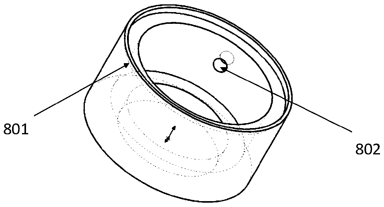
[0076] Step 1: After selecting the stator 8 and the rotor 10 and installing them, adopt the stator 8 and the rotor 10 with a rectangular tooth shape 1002 and a rectangular pressure outlet 802 , and the width of the baffle plate 1003 is larger than the width of the rectangular pressure outlet 802 .
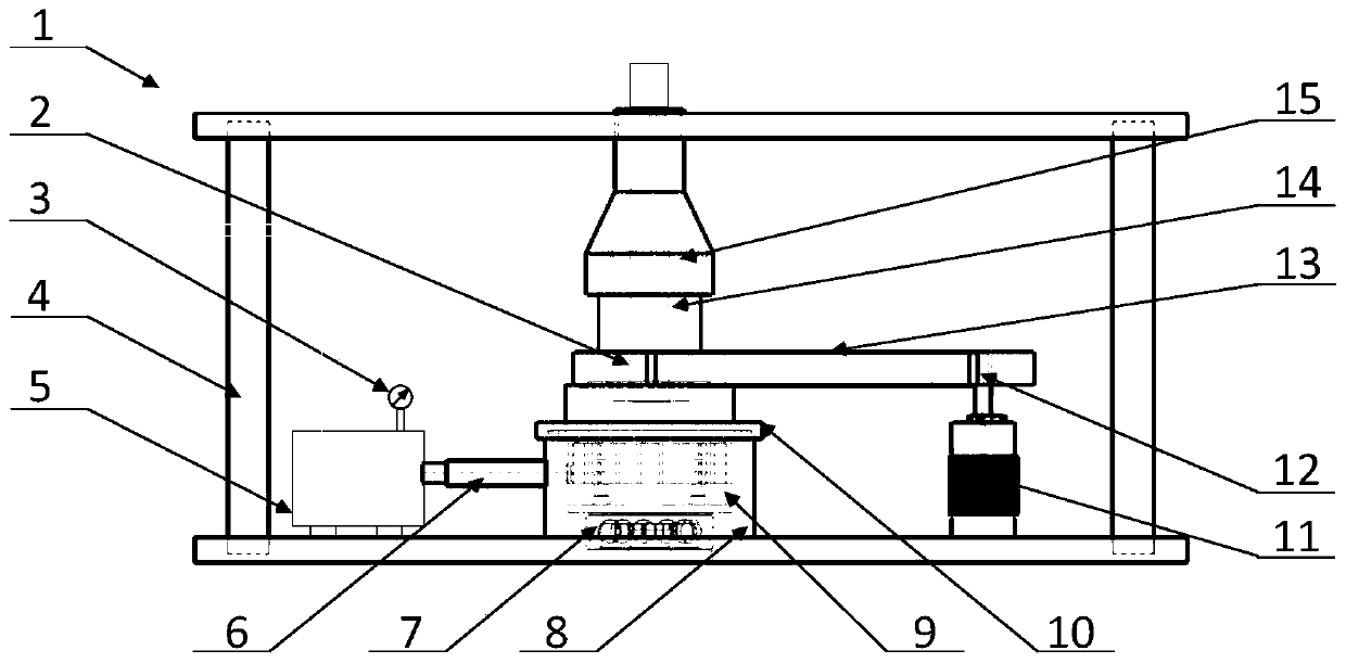
[0077] Step 2: The hydraulic pump 5 is turned on, and the grinding fluid is stably delivered to the inside of the rotor 10 through the hydraulic oil circuit 1, the upper joint 15 and the rotary joint 14, and the stable supply of the specified pressure is realized through the detection of the hydraulic pressure gauge 3.
[0078] Step 3: The baffle plate 1003 of the rotor 10 is opposite to the pressure outlet 802 of the stator 8, thus forming a closed space, the pipeline is disconnected without processing, and the hydraulic p...
Embodiment 2
[0086] Taking the processed workpiece 6 of processing stainless steel as embodiment 2, the specific implementation method is as follows:
[0087] Step 1: After the stator 8 and the rotor 10 are selected and installed, the stator 8 and the rotor 10 adopt the rectangular tooth shape 1002 and the circular pressure outlet 802 or the sine-cosine tooth shape 1002 and the rectangular pressure outlet 802 .
[0088] Step 2: The hydraulic pump 5 is turned on, and the grinding fluid is stably delivered to the inside of the rotor 10 through the hydraulic oil circuit 1, the upper joint 15 and the rotary joint 14, and the stable supply of the specified pressure is realized through the detection of the hydraulic pressure gauge 3.
[0089] Step 3: The baffle plate 1003 of the rotor 10 is opposite to the pressure outlet 802 of the stator 8, thus forming a closed space, the pipeline is disconnected without processing, and the hydraulic pump 5 automatically pumps the grinding fluid when the press...
Embodiment 3
[0097] Take the processed workpiece 6 of industrial pure titanium as embodiment 3, and its specific implementation method is as follows:
[0098] Step 1: After selecting the stator 8 and the rotor 10 and installing them, adopt the stator 8 and the rotor 10 with a rectangular tooth shape 1002 and a rectangular pressure outlet 802 , and the width of the tooth shape 1002 is larger than the width of the pressure outlet 802 .
[0099] Step 2: The hydraulic pump 5 is turned on, and the grinding fluid is stably delivered to the inside of the rotor 10 through the hydraulic oil circuit 1, the upper joint 15 and the rotary joint 14, and the stable supply of the specified pressure is realized through the detection of the hydraulic pressure gauge 3.
[0100] Step 3: The baffle plate 1003 of the rotor 10 is opposite to the pressure outlet 802 of the stator 8, thus forming a closed space, the pipeline is disconnected without processing, and the hydraulic pump 5 automatically pumps the grindi...
PUM
 Abstract
Description
Claims
Application Information
 - R&D
- Intellectual Property
- Life Sciences
- Materials
- Tech Scout
- Unparalleled Data Quality
- Higher Quality Content
- 60% Fewer Hallucinations
Browse by: Latest US Patents, China's latest patents, Technical Efficacy Thesaurus, Application Domain, Technology Topic, Popular Technical Reports.
© 2025 PatSnap. All rights reserved.Legal|Privacy policy|Modern Slavery Act Transparency Statement|Sitemap|About US| Contact US: help@patsnap.com


