
Dual mode drive brakeable device for belt conveyor

A belt conveyor and braking device technology, applied in conveyors, fluid pressure actuating devices, transportation and packaging, etc., can solve problems such as motor power load imbalance, motor overload operation, damage, etc., to achieve stable operation, The effect of large transmission ratio and convenient operation

Active Publication Date: 2020-04-28
SHANDONG UNIV OF SCI & TECH
View PDF18 Cites 0 Cited by
  • Summary
  • Abstract
  • Description
  • Claims
  • Application Information

AI Technical Summary

Problems solved by technology

At present, the commonly used method is dual-motor drive. In an ideal situation, the power distribution ratio is the same as the driving force distribution ratio. However, due to differences in the manufacturing and installation errors of the rollers in actual situations, the motor power load of the two rollers is unbalanced, which is serious. Sometimes it will cause one of the motors to overload and even be damaged, so a dual-mode drive with power balance is required

Method used


Image

  • Dual mode drive brakeable device for belt conveyor
  • Dual mode drive brakeable device for belt conveyor
  • Dual mode drive brakeable device for belt conveyor

Examples


Embodiment Construction

[0025] The specific implementation manners of the present invention will be described in further detail below with reference to the accompanying drawings.

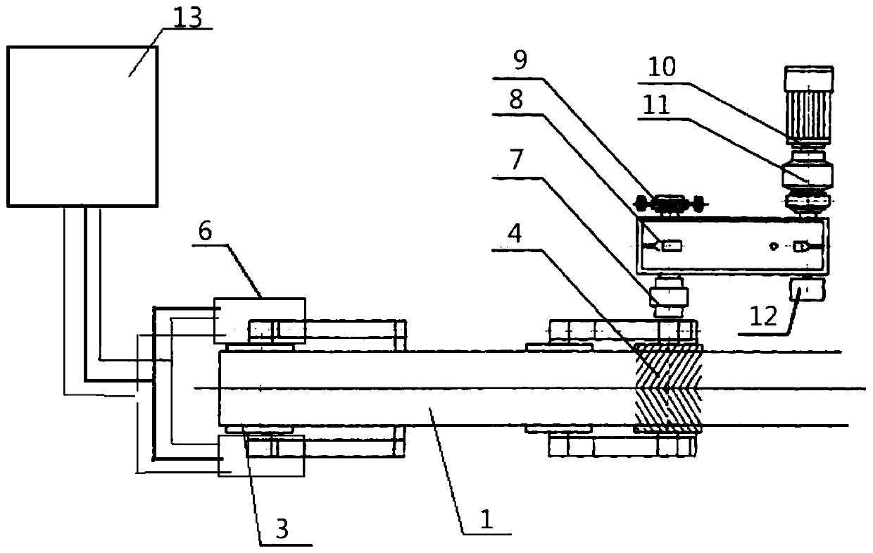
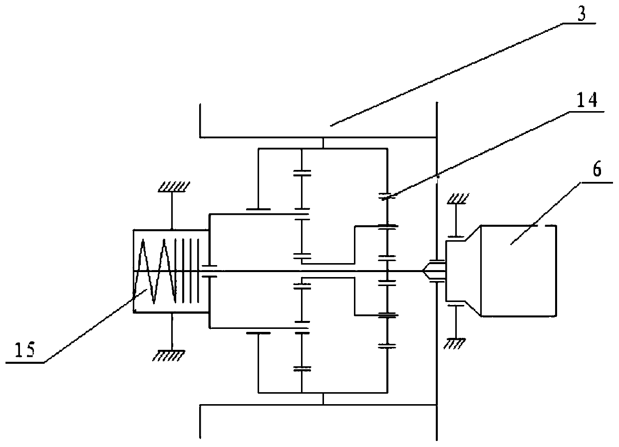
[0026] like Figure 1 to Figure 4 The dual-mode drive brakeable device of the belt conveyor shown includes a hydraulically driven pulley 3 and a motor driven pulley 4. The rotating shaft of the motor driven pulley 4 is connected to a reducer 8 through a coupling 7, and the reducer 8 is connected to a drive Motor 10, hydraulic drive drum 3 is connected with hydraulic motor 6, hydraulic motor 6 is connected with planetary gear reducer 14, the outside of planetary gear reducer 14 is fixed with hydraulic drive drum 3, and the other end of the intermediate shaft of planetary gear reducer 14 is provided with Hydraulic brake 15. The hydraulic brake 15 is a hydraulic normally closed disc brake. The hydraulic motor 6 is connected to the hydraulic station 13. The hydraulic station 13 includes a fuel tank 16, a power oil circuit and ...


PUM


Abstract

The invention relates to a dual-mode drive brake device of a belt conveyor. The dual-mode drive brake device of the belt conveyor comprises a hydraulic drive roller and a motor drive roller; a rotaryshaft of the motor drive roller is connected with a speed reducer through a coupler; the speed reducer is connected with a drive motor; the hydraulic drive roller is connected with a hydraulic motor;the hydraulic motor is connected with a planet gear gearbox; the planet gear gearbox and the hydraulic drive roller are fixed; a middle shaft of the planet gear gearbox is provided with a hydraulic brake; the hydraulic motor is connected with a hydraulic station; the hydraulic station comprises an oil tank, a power oil path and an electro-hydraulic directional control valve; one end of the power oil path is connected with the electro-hydraulic directional control valve; the other end of the power oil path is connected with the oil tank; a brake oil cylinder is connected with a brake oil path;and the brake oil path and a main control oil path are connected with a PLC controller. The problem of unbalance of dual-unit drive power is solved, a hydraulic system can automatically adjust the output torque and rotation speed, and it is ensured that the output force and rotation speeds of drive units are the same completely; and effective brake can be conducted. The hydraulic system can absorbpart of impact loads.

Description

technical field [0001] The invention belongs to the technical field of belt conveyors, and in particular relates to a dual-mode driving brake device of a belt conveyor. Background technique [0002] A belt conveyor is a friction driven machine that transports material in a continuous manner. It is mainly composed of frame, conveyor belt, idler roller, roller, tensioning device, driving device and so on. The traction force of the belt conveyor is transmitted through the friction between the drive roller and the belt, and the drive roller is driven by the drive device. The drive device is actually an energy conversion device, which can be divided into many types according to the possible conversion methods of energy. At present, the commonly used method is dual-motor drive. In an ideal situation, the power distribution ratio is the same as the driving force distribution ratio. However, due to differences in the manufacturing and installation errors of the rollers in actual si...

Claims


Application Information

Patent Timeline
Patent Type & Authority Patents(China)
IPC IPC(8): B65G23/26B65G23/06F15B11/08
CPCB65G23/06B65G23/26F15B11/08
Inventor 姜雪包继华李国清房建梅周生朋刘小龙许飞楚宪省韩越
Owner SHANDONG UNIV OF SCI & TECH
Learn More