
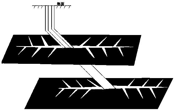
Single well multiple oil layer plane branch multi-crack fracturing technology

A multi-reservoir, multi-fracture technology, applied in the direction of wellbore/well components, production fluid, drilling composition, etc., can solve the problems of short effective and stable period, increase of artificial fracture density, high performance requirements of fracturing fluid, etc., to achieve Good viscoelasticity and fluid loss control, improving production efficiency and benefit, increasing production and recovery

Active Publication Date: 2019-02-19
SHAANXI YOUBANG PETROLEUM ENG TECH CO LTD
View PDF10 Cites 3 Cited by
  • Summary
  • Abstract
  • Description
  • Claims
  • Application Information

AI Technical Summary

Problems solved by technology

However, the conventional vertical well or directional well fracturing technology only creates a simple artificial fracture on each oil and gas layer. The effective area of ​​the fracture and the effect of increasing production and injection are small, the effective stable period is short, and the production declines rapidly, which cannot meet the requirements. Long-term and efficient development of oil and gas fields is required; for horizontal well fracturing technology, although it can improve the production and recovery of oil and gas fields, this technology only increases the density of artificial fractures by carrying out multi-stage fracturing in the horizontal section. Multiple parallel artificial fractures are created, thereby expanding the effective area of ​​artificial fractures in a single well as a whole, but in essence, the effect of expanding the area of ​​action in a single fracture is not expanded. Moreover, multi-stage fracturing of horizontal wells requires a long operating period. The performance requirements for fracturing fluid are high, and it is difficult to flow back fracturing fluid, which is likely to cause great damage to the reservoir, and the flowback fluid usually causes environmental pollution and waste of resources because it cannot be reused. In addition, horizontal well fracturing technology usually It is aimed at single-layer reformation, and cannot reform multiple oil and gas layers

Method used


Image

  • Single well multiple oil layer plane branch multi-crack fracturing technology
  • Single well multiple oil layer plane branch multi-crack fracturing technology
  • Single well multiple oil layer plane branch multi-crack fracturing technology

Examples


Embodiment 1

[0024] A single-well multi-reservoir planar branch multi-fracture fracturing process. The process uses high-viscosity pre-fluid and low-viscosity pre-fluid to inject into the formation in two stages. The mixed fluid of fluid loss agent is used to fracture a number of artificial fractures with a half-length greater than or equal to 300m in the formation as the main fractures, and then inject low-viscosity pre-fluid in the second half, and use the low-viscosity pre-fluid in the second half The friction and shear between the fluid and the wall of the main fracture creates multiple branch fractures on the wall of the main fracture, thereby forming a complex artificial fracture area on the entire reservoir; realizing simultaneous fracturing of multiple reservoirs.

Embodiment 2

[0026] A single-well multi-reservoir planar branch multi-fracture fracturing process, the specific implementation includes the following steps:

[0027] Step 1: Configure high-viscosity pre-fluid, high-efficiency fluid loss control agent and low-viscosity pre-fluid according to the ratio;

[0028] The high-viscosity preflux: is made of 1.5% dimethyl didocosyl ammonium chloride, 0.5% sodium 1-amino-4-naphthalenesulfonate, 1.0% potassium chloride and 97% water according to the above quality It is formed by mixing, wherein the chemical structural formula of dimethyl didocosyl ammonium chloride: [(CH 3 ) 2 N(C 22 h 45 ) 2 】 + Cl - ; The viscosity of the high-viscosity preflush at 25°C is 70-80mPa.

[0029] The high-efficiency fluid loss reducer: it is composed of 60% behenyl amidopropyl dimethyl glyceryl ammonium chloride, 15% rosin, and 25% sodium chloride according to the above mass ratio, with a particle size of 100-180 mesh .

[0030] The low-viscosity pre-fluid is pr...

Embodiment 3

[0035] Substantially the same as Example 2, the difference is: the high-viscosity pre-liquid: is made of 2.5% dimethyl docosyl ammonium chloride, 0.8% 1-amino-4-naphthalene sodium sulfonate, 3.0% Potassium Chloride and 93.7% water are mixed according to the above mass ratio, wherein the chemical structural formula of dimethyl didocosyl ammonium chloride: [(CH 3 ) 2 N(C 22 h 45 ) 2 】 + Cl - ; The viscosity of the high-viscosity preflush at 25°C is 70-80mPa.

[0036] The high-efficiency fluid loss reducer: it is composed of 75% behenyl amidopropyl dimethyl glyceryl ammonium chloride, 20% rosin, and 5% sodium chloride according to the above mass ratio, with a particle size of 100-180 mesh .

[0037] The low-viscosity pre-fluid is prepared by diluting the high-viscosity pre-fluid with clear water by 1 time; wherein, the viscosity of the low-viscosity pre-fluid at 25°C is 10-25mPa.


PUM

PropertyMeasurementUnit
Particle sizeaaaaaaaaaa

Abstract

The invention discloses a single well multiple oil layer plane branch multi-crack fracturing technology. High-viscosity ahead fluid and low-viscosity ahead fluid with different viscosities are adopted, the single well multiple oil layer plane branch multi-crack fracturing technology is divided into two segments and injected into the stratum, the front semi-segment is injected with mixing fluid ofthe high-viscosity ahead fluid and a high-efficient fluid loss agent, a plurality of cracks with half-length greater than or equal to 300 m of artificial cracks are fractured in the stratum to be usedas main cracks, then the low-viscosity ahead fluid is injected into a rear semi-segment, and fraction shear of the low-viscosity ahead fluid of the rear semi-segment and the main crack wall surfacesis used for building a plurality of branch cracks on the main crack wall surfaces, so that a complex artificial crack area is formed on a whole reservoir stratum; and fracture of a plurality reservoirs at the same time is realized.

Description

technical field [0001] The invention relates to a fracturing technology, in particular to a single-well multi-oil layer plane branch multi-fracture fracturing technology. It belongs to the technical field of oil and gas field production and development. Background technique [0002] In the field of oil and gas field development technology, fracturing technology is an extremely important production and injection technology, especially in the development of low permeability oil and gas reservoirs, it plays a very important role in improving the production and recovery of oil and gas fields. However, the conventional vertical well or directional well fracturing technology only creates a simple artificial fracture on each oil and gas layer. The effective area of ​​the fracture and the effect of increasing production and injection are small, the effective stable period is short, and the production declines rapidly, which cannot meet the requirements. Long-term and efficient deve...

Claims


Application Information

Patent Timeline
IPC IPC(8): E21B43/26C09K8/68
CPCC09K8/68E21B43/26
Inventor 肖良飞陈柯全刘畅
Owner SHAANXI YOUBANG PETROLEUM ENG TECH CO LTD
Learn More