Optical module, optical module emitting optical device and preparation method thereof

An optical module and a technology for emitting light, applied in the field of optical communication, can solve the problems of reducing the preparation efficiency, complexity, and cumbersome process, and achieve the effects of improving the preparation efficiency, reducing the preparation cost, and reducing the coupling complexity.

Pending Publication Date: 2019-02-19
DONGGUAN MENTECH OPTICAL & MAGNETIC CO LTD
View PDF8 Cites 4 Cited by
  • Summary
  • Abstract
  • Description
  • Claims
  • Application Information

AI Technical Summary

Problems solved by technology

[0004] It can be seen from the above process that the process of lens coupling and fiber coupling is cumbersome and complicated, so it will increase the preparation time and reduce the preparation efficiency
In addition, in the lens coupling, since the automatic lens coupling machine and laser welding machine used are relatively expensive, it will lead to an increase in the production cost of the product

Method used


Image

  • Optical module, optical module emitting optical device and preparation method thereof
  • Optical module, optical module emitting optical device and preparation method thereof
  • Optical module, optical module emitting optical device and preparation method thereof

Examples


Embodiment Construction

[0029] The following will clearly and completely describe the technical solutions in the embodiments of the present invention with reference to the accompanying drawings in the embodiments of the present invention. Obviously, the described embodiments are only some, not all, embodiments of the present invention. Based on the embodiments of the present invention, all other embodiments obtained by persons of ordinary skill in the art without making creative efforts belong to the protection scope of the present invention.

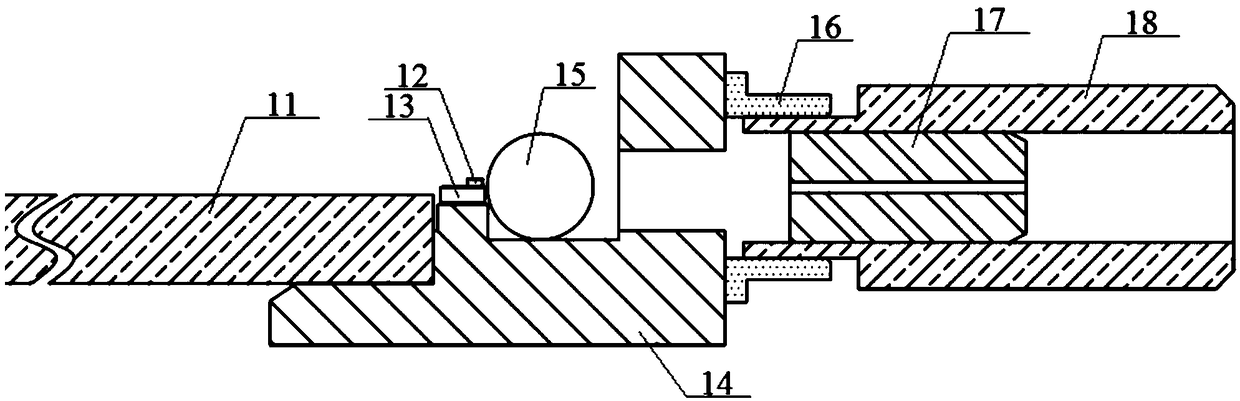
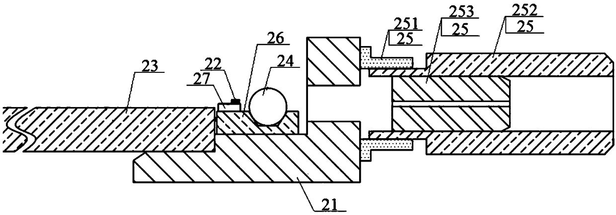
[0030] See figure 2 , which shows a schematic structural view of an optical module emitting light device provided by an embodiment of the present invention, which may include a base 21, a laser chip 22, a PCB 23 connected to the laser chip 22, a lens 24, and a laser chip 22 coupled and fixed The light output member 25 on the base 21 may also include a substrate 26 fixed on the base 21 and having a U-shaped groove at a preset position, the substrate 26 has the...


PUM


Abstract

The invention discloses an optical module, an optical module emitting optical device and a preparation method thereof. The optical module emitting optical device comprises a base, a laser chip, a PCBconnected to the laser chip, a lens, and a light-emitting member connected to the laser chip and fixed on the base. The invention further comprises a substrate fixed on the base and provided with a U-shaped groove at a preset position. The substrate has thermal conductivity. The laser chip is fixed on the surface of the substrate. The lens is fixed in a U-shaped groove at a preset position. The preset position is a position where the optical power of the laser chip obtained by optical simulation is the largest. The above technical solution disclosed in the present application can directly fixthe lens in the U-shaped groove of the substrate without coupling and fixing the lens by the automatic lens coupling machine and the laser welding machine. Therefore, the coupling complexity of the optical module emitting optical device can be reduced, the preparation efficiency of the optical module emitting optical device can be improved, and the manufacturing cost of the optical module emittingoptical device can be reduced.

Description

technical field [0001] The invention relates to the technical field of optical communication, and more specifically relates to an optical module, an optical module emitting light device and a preparation method thereof. Background technique [0002] With the rapid development of optical communication technology, the data transmission speed of optical modules has increased from 10G, 25G, and 40G to the current 100G, 200G, and 400G. The 100G (or 200G, 400G) optical module emitter includes four channels, and the structure of each channel can be found in figure 1 , which shows a schematic structural view of the channel of an existing optical module emitting optical device, mainly including a PCB (Printed Circuit Board, printed circuit board) 11, a laser chip 12, a heat sink 13, a metal base 14, a lens 15, and an adjustment ring 16 And the metal lower sleeve 18 with optical fiber 17, the corresponding working process is that the external circuit powers the gold finger of PCB11 t...

Claims


Application Information

Patent Timeline
Patent Type & Authority Applications(China)
IPC IPC(8): G02B6/42
CPCG02B6/4204G02B6/4244G02B6/4245G02B6/4296
Inventor 杨智王艳红
Owner DONGGUAN MENTECH OPTICAL & MAGNETIC CO LTD
Why Eureka
Try Eureka