Linear array laser coherent mirror

A linear array laser and optical waveguide technology, applied in the direction of lasers, laser components, phonon exciters, etc., can solve the problems of poor coherence, poor stability, and high cost of linear array lasers, and achieve high beam quality, high coherence efficiency, and The effect of improving stability

Active Publication Date: 2018-01-02
吉光半导体科技有限公司
View PDF2 Cites 0 Cited by
  • Summary
  • Abstract
  • Description
  • Claims
  • Application Information

AI Technical Summary

Problems solved by technology

[0008] The purpose of the present invention is to propose a linear array laser coherent mirror and its preparation method, to solve the problems of poor coherence, poor stability, low power and high cost of linear array lasers existing in the prior art

Method used


Image

  • Linear array laser coherent mirror
  • Linear array laser coherent mirror
  • Linear array laser coherent mirror

Examples


Embodiment 1

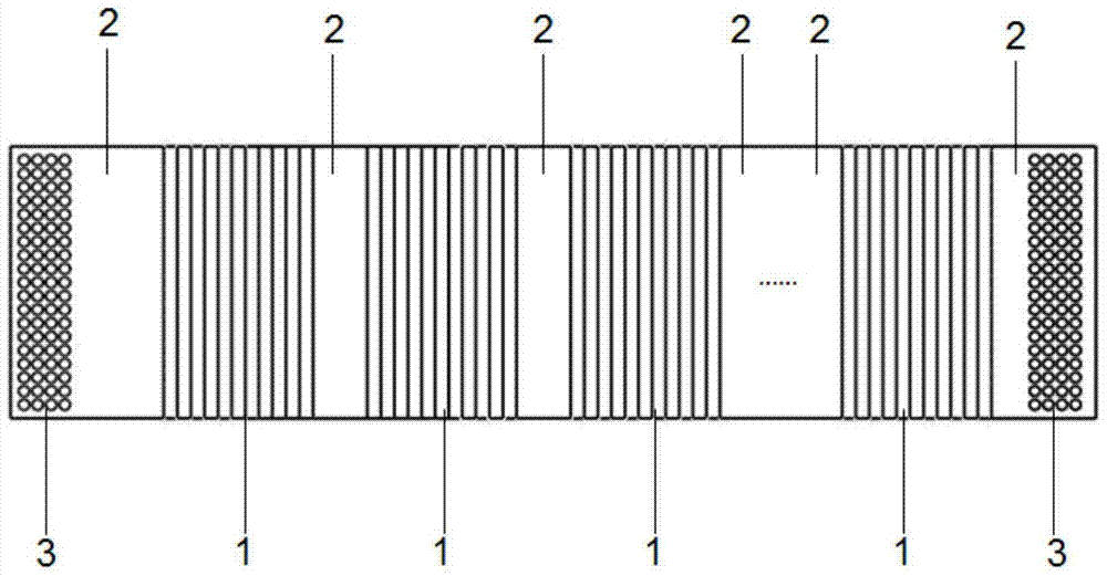
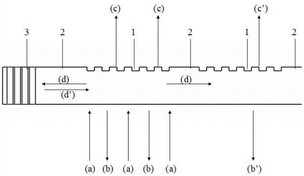
[0039] See attached figure 1 , the linear array laser coherent mirror of the present invention includes n diffraction gratings 1 and n+1 optical waveguides 2 that are alternately connected, and on both sides of the structure formed by the diffraction grating 1 and the optical waveguide 2, a waveguide reflection structure 3 is prepared; the diffraction grating 1 Diffraction can be performed on the laser light in the selected band, the optical waveguide 2 is above the cut-off frequency, and the optical mode transmission of the laser light in this band can be realized, and the waveguide reflection structure 3 can reflect the optical mode in the optical waveguide 2 .

[0040] The value range of n is: n≥1.

[0041] The diffraction grating 1 is grown or etched on the optical waveguide 2 .

[0042] The waveguide reflective structure 3 is an optical structure that can be used to reflect the optical modes transmitted in the optical waveguide 2 .

[0043] The waveguide reflection stru...

Embodiment 2

[0057] The difference between the present embodiment and the first embodiment is that, according to the actual process conditions, the order of the second step and the third step are interchanged. The preparation method obtained after the interchange comprises the following steps:

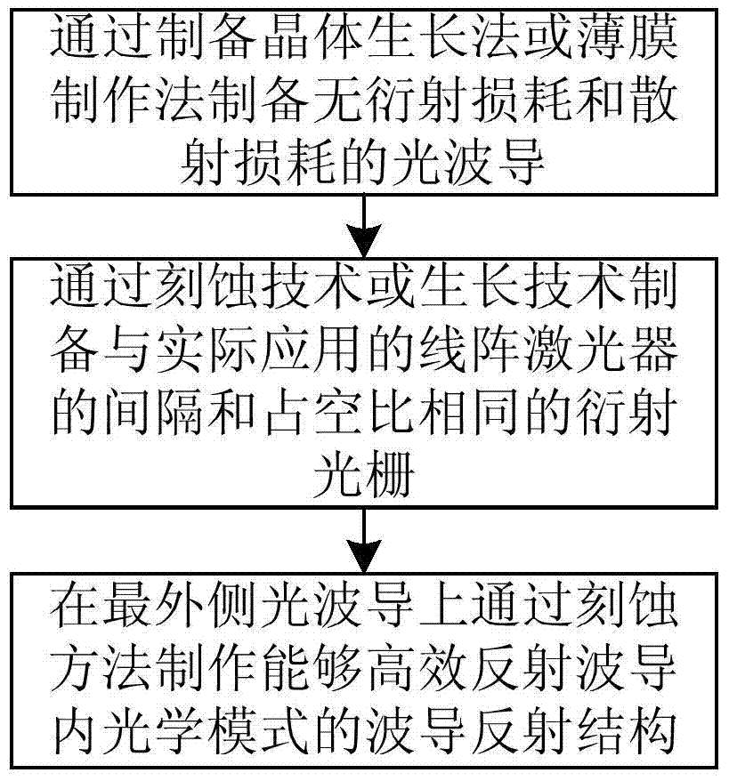
[0058] Step 1: For the wavelength band of the linear array laser used, select a transparent material in this band, and prepare the optical waveguide 2 without diffraction loss and scattering loss through the crystal growth method or thin film manufacturing method. The size and structure of the optical waveguide 2 should make its own The cutoff frequency is smaller than the selected band;

[0059] Step 2: Designate the position where the diffraction grating (1) needs to be fabricated and the position of the optical waveguide (2) connected to it, and fabricate a waveguide reflector that can reflect the optical mode in the waveguide by etching on the outermost optical waveguide 2 Structure 3;

[006...


PUM


Abstract

The linear array laser coherent mirror and the preparation method thereof belong to the technical field of laser coherent coupling, aiming at solving the problems of poor coherence, poor stability, low power and high cost of the linear array laser existing in the prior art. The linear array laser coherent mirror of the present invention includes n diffraction gratings and n+1 optical waveguides which are connected alternately, and waveguide reflection structures are prepared on both sides of the structure formed by the diffraction gratings and optical waveguides. The preparation method of the linear array laser coherent mirror, firstly, the optical waveguide is prepared by the crystal growth method or the thin film manufacturing method; secondly, the optical waveguide prepared in step 1 is prepared by the growth method or the etching method and the actual application of the linear array laser. Diffraction gratings with the same interval and duty ratio; finally, a waveguide reflective structure that can efficiently reflect the optical mode in the waveguide is fabricated on the outermost optical waveguide by etching. The invention utilizes the diffraction grating to realize mutual injection and phase locking of photons, thereby realizing optical coherence, improving light brightness and narrowing line width.

Description

technical field [0001] The invention belongs to the technical field of laser coherent coupling, and in particular relates to a line-array laser coherent mirror for performing phase-locking and coherence on each light-emitting unit in a line-array laser and a preparation method thereof. Background technique [0002] Compared with single-tube lasers, linear array lasers are widely used because they can obtain higher power. However, with the development of science and technology, more and more fields require high beam quality, high brightness, narrow linewidth, and high coherence. The demand for high-power lasers continues to grow. [0003] For general linear array lasers, since the photons between each light-emitting unit in the linear array cannot be injected into each other, there is no coherence, which leads to wide laser linewidth, poor mode characteristics, large far-field divergence angle, and high Low, can not realize the shortcomings of phase locking, which limits its...

Claims


Application Information

Patent Timeline
Patent Type & Authority Patents(China)
IPC IPC(8): H01S3/10
Inventor 陈泳屹秦莉宁永强王立军佟存柱刘云
Owner 吉光半导体科技有限公司
Why Eureka
Try Eureka