Static rotational flow emulsion-breaking device and application thereof

A demulsification device and electrostatic technology, which is applied in the application field of demulsification treatment, can solve the problems of affecting the working stability of the device, reducing the collision frequency of water droplets, and worsening the coalescence effect, so as to achieve the enhancement of swirl strength and the increase of residence time. , the effect of improving the efficiency of aggregation

Active Publication Date: 2019-02-22
CHENGDU UNIVERSITY OF TECHNOLOGY
View PDF8 Cites 9 Cited by
  • Summary
  • Abstract
  • Description
  • Claims
  • Application Information

AI Technical Summary

Problems solved by technology

Although this device can improve the coalescence of water droplets in the water-in-oil emulsion through the synergistic effect of the electric field and the swirl field, there are the following problems: 1. Since the coalescence main body is a cylinder with the same inner diameter of the upper part and the lower part, and The inlet pipe is set on the left side of the upper part of the cylinder, so the swirl velocity from top to bottom of the emulsion entering the coalescing body will slow down under the influence of flow resistance, resulting...

Method used


Image

  • Static rotational flow emulsion-breaking device and application thereof
  • Static rotational flow emulsion-breaking device and application thereof
  • Static rotational flow emulsion-breaking device and application thereof

Examples


Embodiment 1

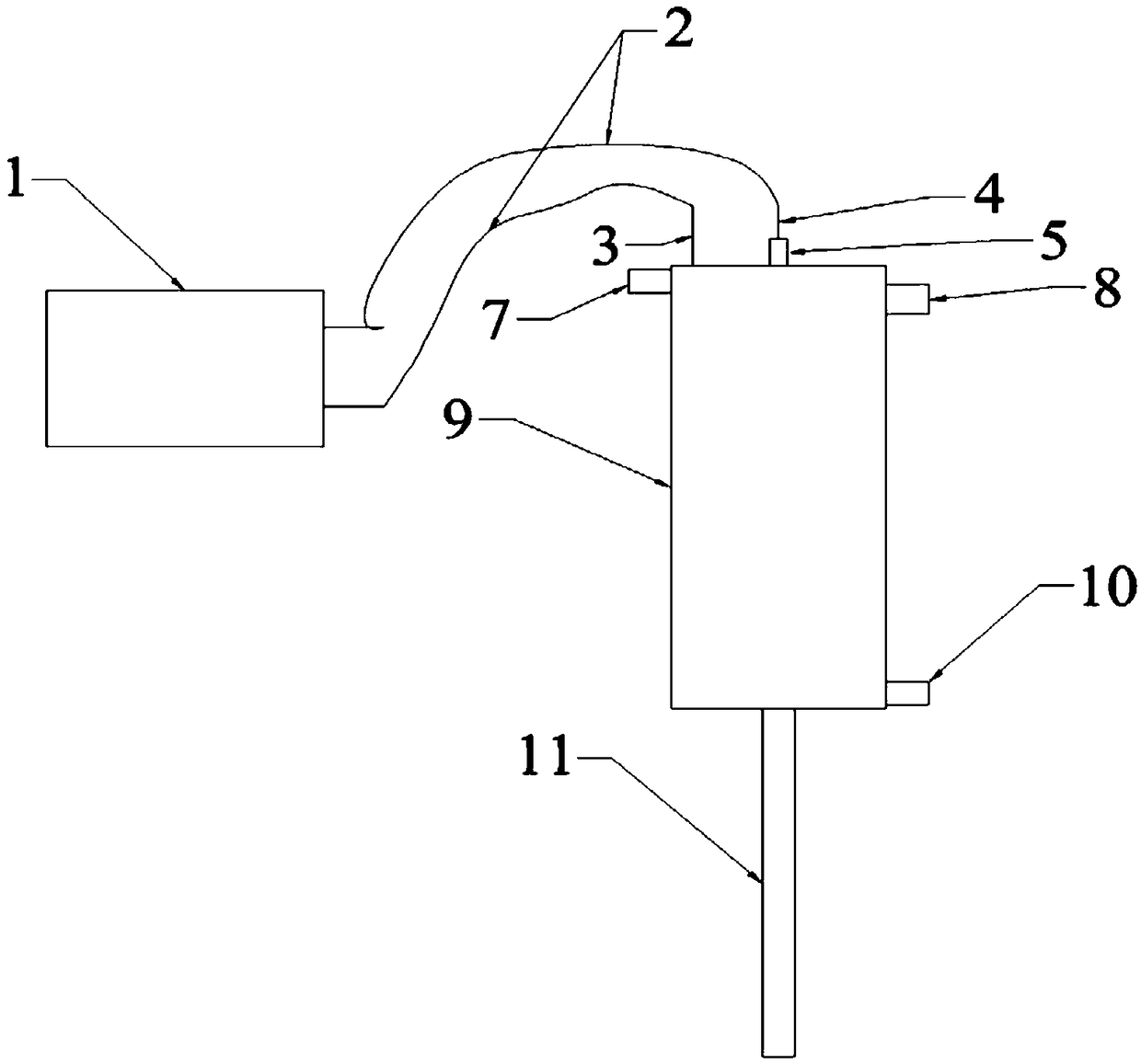
[0028] In this embodiment, the electrostatic cyclone demulsification device such as figure 1 , figure 2 , image 3 As shown, it includes an insulating demulsification main body, an insulating shell 9, an electrode assembly and a power generator 1. Power generator 1 is mainly composed of a high-voltage pulse power supply (Guangxin JC-12) and a signal generator (MFG-3005CH). The signal generator is used to input waveform signals to the high-voltage pulse power supply. Output high voltage pulse signal after waveform signal.

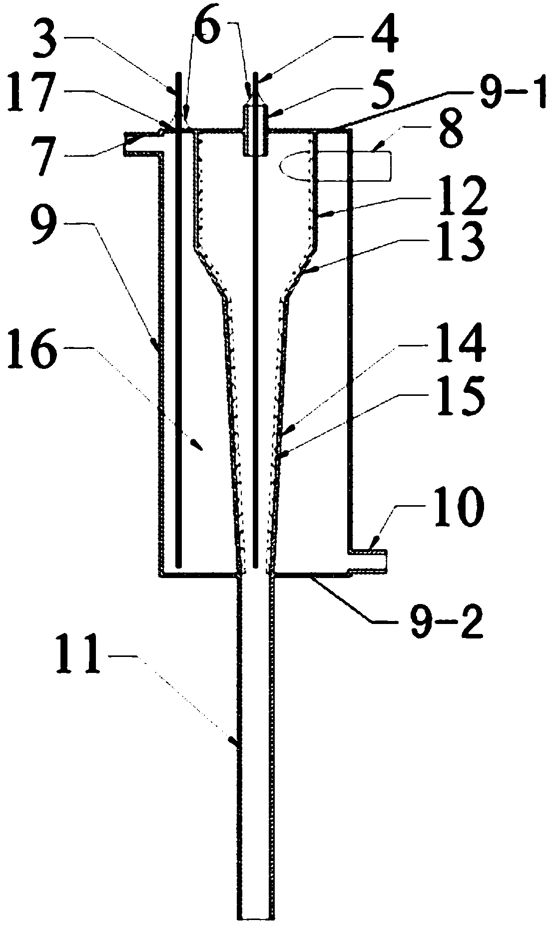
[0029] Such as image 3 As shown, the electrode assembly is composed of a first insulated electrode 3 and a second insulated electrode 4 .

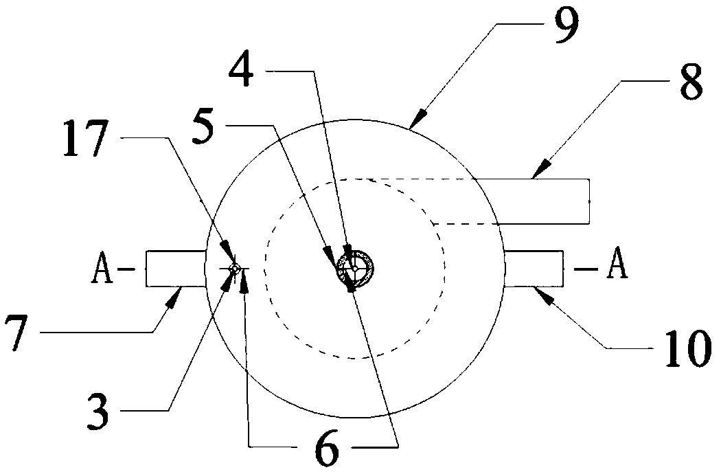
[0030] Such as image 3 , Figure 4 As shown, the insulating demulsification main body is composed of a cylindrical section chamber 12, a first cone section chamber 13, a second cone section chamber 14 and a tailpipe 11 whose center line is on a straight line from top to bottom; the cylindrical section chamber T...

Embodiment 2

[0034] In this example, the electrostatic cyclone demulsification device described in Example 1 is used to break the water-in-oil emulsion with the mixture of kerosene and tributyl phosphate as the continuous phase and wet-process phosphoric acid as the dispersed phase. The water-in-oil emulsion is composed of 1000mL kerosene, 1500mL tributyl phosphate and 500mL wet-process phosphoric acid, with a volume of 3000mL.

[0035] Demulsification treatment operation:

[0036] ①Inject 2000mL of NaCl solution with a mass concentration of 1.0% into the annular cavity 16 between the outer wall of the insulating demulsification main body and the inner wall of the insulating shell, then turn on the power generator 1, and adjust the pulse electric field strength and frequency to 5kV / cm and 800Hz;

[0037] ②The above-mentioned water-in-oil emulsion is input into the insulating demulsification main body from the feed pipe 8 at a volume flow rate of 12.8L / min, and under the action of centrifu...

Embodiment 3

[0043] In this embodiment, the electrostatic cyclone demulsification device such as figure 1 , figure 2 , image 3 , Figure 4 As shown, it includes an insulating demulsification main body, an insulating shell, an electrode assembly and a power generator.

[0044] The difference from Example 1 is:

[0045] 1. Relevant dimensions of the demulsification main body: the height L1=40mm, the inner diameter D=20mm of the cylindrical section chamber 12, the inner diameter Do=4mm of the overflow pipe, the length extending into the cylindrical section chamber=8mm, the length of the feed pipe Inner diameter Di=8mm; The inner diameter of the first taper section chamber 13 upper ends is identical with the inner diameter D of the cylindrical section chamber, the inner diameter D1=10mm of the lower end, cone angle α=20 °; The inner diameter of the second taper section chamber 14 upper ends is the same as The inner diameter D1 of the lower end of the chamber of the first cone section is ...


PUM


Abstract

The invention discloses a static rotational flow emulsion-breaking device. The static rotational flow emulsion- breaking device comprises an insulated emulsion-breaking body, an insulated shell, an electrode assembly and a power source generator; the electrode assembly is composed of a first insulated electrode and a second insulated electrode, the insulated emulsion-breaking body is composed of acylindrical section cavity, a first conical section cavity, a second conical section cavity and a tail pipe sequentially from top to bottom, and the inner wall of the cylindrical section cavity, theinner wall of the first conical section cavity and the inner wall of the second conical section cavity are lined with hydrophilic materials; the first insulated electrode is inserted into an annular cavity body of between the outer wall of the insulated emulsion-breaking body and the inner wall of the insulated shell, and the second insulated electrode is inserted into the cylindrical section cavity, the first conical section cavity and the second conical section cavity of the insulated emulsion-breaking body; and the power source generator is placed outside the insulated shell and connected with the first insulated electrode and the second insulated electrode through insulated wires. The static rotational flow emulsion-breaking device is applied to emulsion-breaking treatment of water-in-oil emulsion, the collision frequency of water drops in the emulsion can be increased, and the coalescence efficiency of the water drops, using safety and using stability are improved.

Description

technical field [0001] The invention belongs to the technical field of oil-water two-phase separation, and particularly relates to a demulsification device for accelerating water droplet aggregation and demulsification through the synergistic effect of an electrostatic field, a centrifugal force field, and a hydrophilic material, and in the demulsification treatment of a water-in-oil emulsion Applications. Background technique [0002] Emulsion is a multiphase dispersion system with considerable stability, in which the phase existing in the form of droplets is called the dispersed phase, and correspondingly, the other phase is called the continuous phase. If the dispersed phase is an organic liquid and the continuous phase is water or an aqueous solution, then such an emulsion is called an oil-in-water (O / W) emulsion; on the contrary, if the dispersed phase is water or an aqueous solution, the continuous phase is an organic liquid , then such emulsions are called water-in-o...

Claims


Application Information

Patent Timeline
IPC IPC(8): B01D17/06B01D17/038B01D17/022
CPCB01D17/0202B01D17/0217B01D17/06
Inventor 曹语晴金央李军
Owner CHENGDU UNIVERSITY OF TECHNOLOGY
Why Eureka
Try Eureka