Biological culture reaction device

A reaction device and biological culture technology, applied in the field of biological culture reactors, can solve problems such as human error, increased pollution risk, difficult handling, etc., and achieve the effect of improving use efficiency

Pending Publication Date: 2019-02-22
刘延群
View PDF2 Cites 1 Cited by
  • Summary
  • Abstract
  • Description
  • Claims
  • Application Information

AI Technical Summary

Problems solved by technology

The operation is complex, prone to human error, resulting in liquid leakage, once the liquid leaks, it will cause pollution
The integrated design does not allow routine liquid changes every other day, and cannot meet the nutritional conditions of the cell and tissue culture environment
The integrated design results in a bulky pressurized chamber that carries cultured tissues in the incubator for long-term cultivation. The humid and hot environment in the incubator causes rapid aging of components, reduces the stability of the equipment, and increases the risk of contamination
The integrated design makes the operation of putting cells and tissues into the reactor and taking them out of the reactor complicated, and it is an operation with a high risk of contamination
Integrated design, in order to achieve the safety conditions of the internal pressurized chamber in a high-pressure environment, the reactor is designed to be heavy, and it is difficult to carry and operate for practical operation

Method used


Image

  • Biological culture reaction device
  • Biological culture reaction device
  • Biological culture reaction device

Examples


Embodiment Construction

[0020] The present invention will be further described below in conjunction with the accompanying drawings and embodiments.

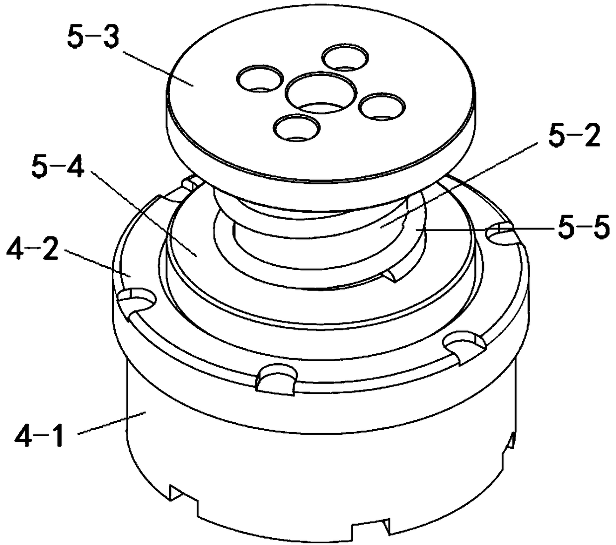
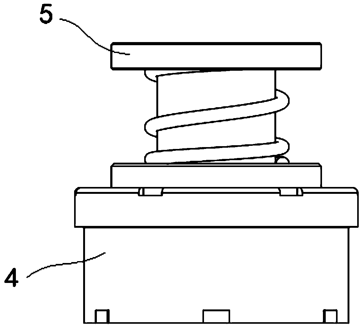
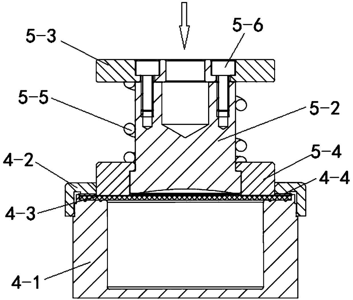
[0021] like Figure 1 to Figure 4 As shown, a biological culture reaction device includes a culture cabin 4 and a pressurizing assembly 5, and the pressurizing assembly 5 is composed of an inner pressure head 5-2, an upper pressing plate 5-3, a lower pressing plate 5-4, and a compression spring 5-5 . The upper end surface of the inner pressure head 5-2 is fixedly connected to the upper pressure plate 5-3 with bolts 5-6, the lower end of the inner pressure head 5-2 is sleeved with the lower pressure plate 5-4, and the lower part of the inner pressure head 5-2 is provided with a boss, The upper end of the through hole of the lower pressing plate 5-4 is provided with a convex ring, and the lower pressing plate 5-4 cooperates with the boss at the bottom of the inner pressure head 5-2 for axial positioning through the convex ring, so that the lower pressing...


PUM


Abstract

The invention relates to a biological culture reaction device. The biological culture reaction device comprises a culture bin and a pressurizing assembly, wherein the pressurizing assembly comprises an inner pressure head, an upper pressure plate, a lower pressure plate and a pressure spring, wherein the upper pressure plate is fixedly connected to the upper end surface of the inner pressure headthrough a bolt, the lower end of the inner pressure head is sleeved with the lower pressure plate, a lug boss is arranged at the lower part of the inner pressure head, a protruded ring is arranged atthe upper end of a through hole of the lower pressure plate, the lower pressure plate is axially positioned through the cooperation between a protruded ring and the lug boss at the lower part of the inner pressure head and then can move upwards together with the inner pressure head; the inner pressure head is externally sleeved with the pressure spring, and two ends of the pressure spring are respectively in contact connection with the upper pressure plate and the lower pressure plate; and the inner pressure head and the lower pressure plate are respectively in pressure contact connection witha silica gel film piece in the culture bin, the lower pressure plate is used for compressing the silica gel film piece to the upper end surface of a culture tank body so as to tightly seal the spacebetween the silica gel film piece and the upper end surface of the culture tank, and the inner pressure head is used for supplying a preset pressure to a liquid in the culture tank through the silicagel film piece. The biological culture reaction device can be applied to an automatic biological reaction tester, and the pollution caused by a reactor can be furthest reduced.

Description

technical field [0001] The invention relates to a bioreactor, in particular to a biological cultivation reactor, and belongs to the technical field of bioreactors. Background technique [0002] A bioreactor is an experimental tool used to cultivate biological cells and tissues. It provides cells and tissues with a high-pressure culture environment for 1 hour a day. One blow, aseptic (this is the basis of cell culture), sufficient nutritional environment (including the supply of nutrients (the degradation rate of various cells must be fast) and the removal of waste), to meet the needs of biological tissues every other day liquid. [0003] Integrated bioreactor with existing circulation system and pressurization system. Such as patent publication number CN103589638B, a pneumatic self-circulation animal cell culture bioreactor and its use method, the magnetic stirring system, heating system and control system located at the bottom of the large tank, the upper end of the large...

Claims


Application Information

Patent Timeline
Patent Type & Authority Applications(China)
IPC IPC(8): C12M1/36C12M1/00C12M3/00
CPCC12M37/04C12M41/40
Inventor 刘延群周广东李平夏会堂徐勇刘春燕
Owner 刘延群
Why Eureka
Try Eureka