Chemical vapor deposition method device

A chemical vapor deposition, heating device technology, applied in gaseous chemical plating, metal material coating process, coating and other directions, can solve problems such as small area, and achieve the effect of increasing area, increasing fluidity, and maintaining integrity

Inactive Publication Date: 2019-02-22
UNIV OF ELECTRONICS SCI & TECH OF CHINA
View PDF9 Cites 0 Cited by
  • Summary
  • Abstract
  • Description
  • Claims
  • Application Information

AI Technical Summary

Problems solved by technology

[0005] The purpose of the present invention is to provide a chemical vapor deposition method device to solve the problem that the existing two-dimensional material film has a small area during preparation

Method used


Image

  • Chemical vapor deposition method device
  • Chemical vapor deposition method device
  • Chemical vapor deposition method device

Examples


Embodiment 1

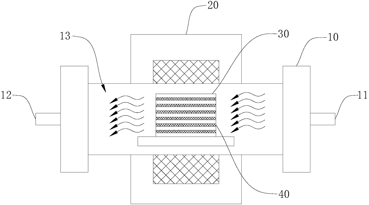
[0037] Please refer to figure 1 , a chemical vapor deposition method device, comprising: a reaction furnace 10 and a heating device 20 . The reaction furnace 10 is a horizontal tube furnace with a reaction chamber 13 inside and an air inlet 11 and an air outlet 12 at both ends for the circulation of gases such as protective gas and gaseous precursors. The heating device 20 is arranged around the reaction furnace 10 for raising the temperature of the reaction furnace 10 . The reaction chamber 13 is provided with a support platform on which a multi-layer metal substrate 30 is placed. In this embodiment, the metal base 30 is copper foil with a thickness of 100 μm. In other embodiments of the present invention, the reaction furnace 10 can also be a vertical tube furnace, etc., and the heating device 20 can be matched with the corresponding reaction furnace 10; the metal base 30 can also be made of materials such as nickel, iron, cobalt, gold, silver, Metals such as platinum and...

Embodiment 2

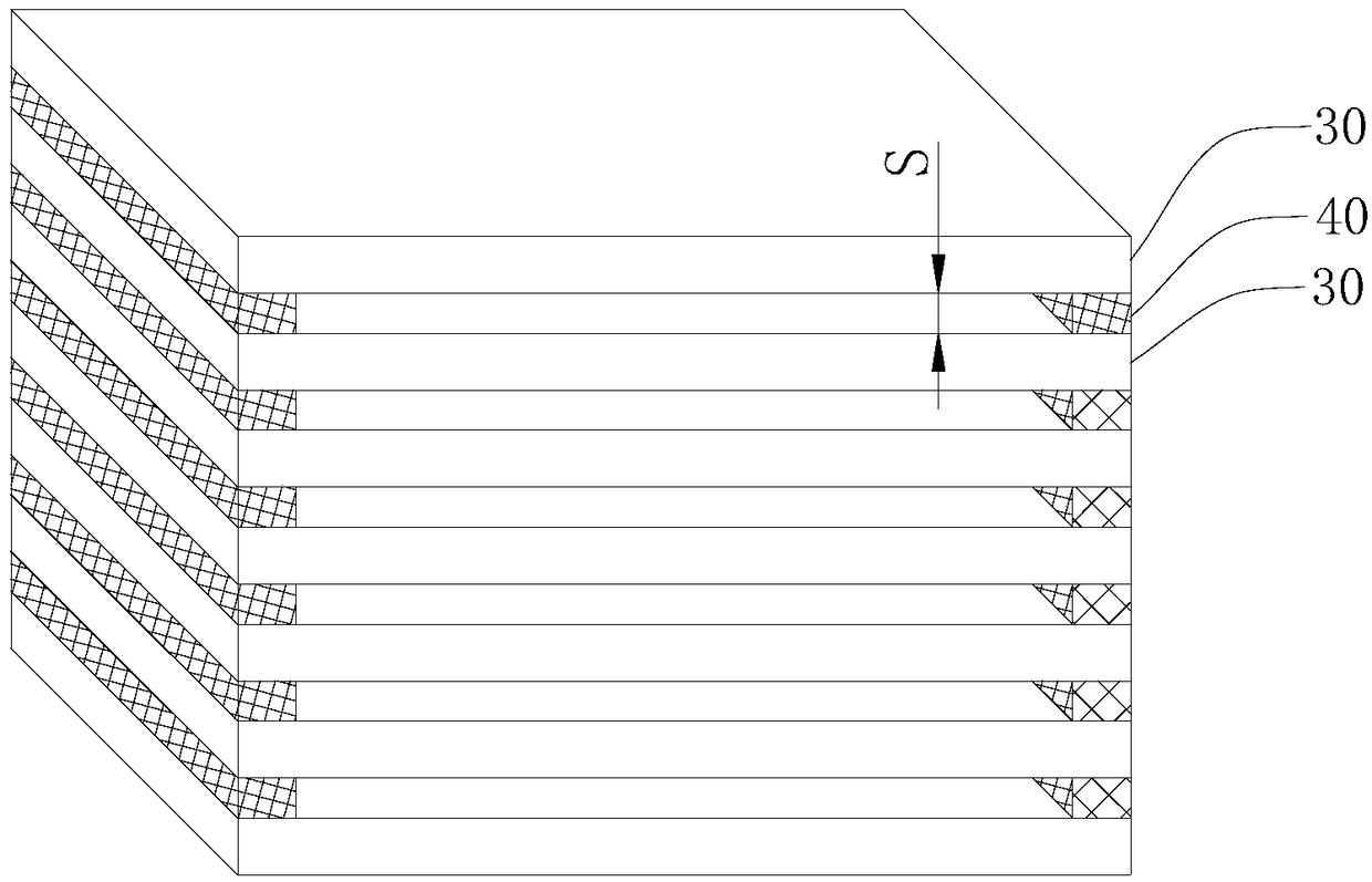
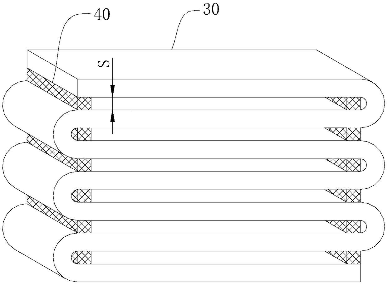
[0040] Please refer to Figure 4  ̄ Figure 6 The difference between this embodiment and Embodiment 1 is that the metal base 30 is spirally formed into multiple layers, and the strip-shaped metal base 30 is wound along the outer surface of the mandrel 50, so that the metal base 30 is in a multi-layer spiral shape. A spacer 40 is provided between the metal bases 30 on adjacent sides, and the spacer 40 is arranged on the curled edge of the metal base 30, that is, when the metal base 30 is not wound, the spacer 40 is set on the edge of the metal base 30 that needs to be curled, and the The metal base 30 provided with the spacers 40 is wound around the mandrel 50 to form a spiral in multiple layers. The axis of the helical metal base 30 is consistent with the connecting direction of the air inlet 11 and the air outlet 12 , so that the precursor can smoothly enter the cavity between the metal bases 30 on adjacent sides.

[0041] The process of preparing two-dimensional material gr...


PUM

PropertyMeasurementUnit
widthaaaaaaaaaa
thicknessaaaaaaaaaa

Abstract

The invention discloses a chemical vapor deposition method device, and belongs to the technical field of preparation of two-dimensional materials. The chemical vapor deposition method device comprisesa reaction furnace and a heating device, wherein the heating device is arranged around the reaction furnace, the two ends of the reaction furnace are correspondingly provided with an air inlet and anair outlet, a reaction chamber is arranged inside the reaction furnace, a plurality of layers of metal substrates are arranged in the reaction chamber, and a porous separation strip is arranged between the edges of every two adjacent metal substrates, so that a gap S is formed between every two adjacent layers of metal substrates. According to the chemical vapor deposition method device, under the conditions that a precursor which is not blocked and in a gas state is circulated, and meanwhile high-temperature sintering or adhesion of the metal substrates is avoided, the space of the reactionchamber is fully utilized, the area used for allowing the metal substrates to be placed is increased, then the area of a two-dimensional material thin film which can be formed is increased, and the device is suitable for industrial production and preparation; and in addition, the two-dimensional material thin film prepared through the device has continuity, can have a large macroscopic area and issuitable for application in the aspects of industry, research and the like.

Description

technical field [0001] The invention relates to the technical field of preparation of two-dimensional materials, in particular to a chemical vapor deposition method device. Background technique [0002] When layered materials are less than a few atoms thick, they are called two-dimensional materials. At present, two-dimensional materials are a hotspot of scientific research. They have very superior properties and have great prospects in semiconductors and other fields. [0003] The chemical vapor deposition (CVD) method is a typical method for preparing two-dimensional material thin films. This method generally uses a metal foil as a substrate, and the precursor is catalytically cracked on the metal substrate, and deposited to form a thin film. For example, the CVD method prepares graphene by heating the substrate to thousands of degrees, passing through hydrocarbons, which crack and deposit graphene on the substrate, and the system is cooled to room temperature after the r...

Claims


Application Information

Patent Timeline
Patent Type & Authority Applications(China)
IPC IPC(8): C23C16/458C23C16/26C23C16/02
CPCC23C16/0209C23C16/26C23C16/4581
Inventor 李雪松王跃青芳竹
Owner UNIV OF ELECTRONICS SCI & TECH OF CHINA
Why Eureka
Try Eureka