Cutter-changing machine clamping claw for single hob of shield machine

A technology of mechanical gripper and shield machine, which is applied to manipulators, program-controlled manipulators, chucks, etc., can solve the problems of large volume and weight of hob, inability to meet loading and unloading paths, and difficulty for workers to change tools, so as to achieve a simple replacement path. , The effect of saving space utilization and moderate volume

Pending Publication Date: 2019-02-22
QINGDAO UNIV OF SCI & TECH
View PDF0 Cites 4 Cited by
  • Summary
  • Abstract
  • Description
  • Claims
  • Application Information

AI Technical Summary

Problems solved by technology

[0002] Shield machines are widely used in underground rail transit, water pipelines, power tunnels and other projects, while shield machines with single-edged hobs are mainly used in rock tunnel excavation and other projects; long-term work will cause a certain degree of wear on the cutter , it is necessary to open the cabin regularly to check and replace the cutting tool. Due to the harsh working environment and high-pressure sealing, workers will have great difficulties and dangers in the tool changing operation, and the use of robots to replace hobs has attracted increasing attention.
[0003] However, due to the large size and weight of the hob, the path of disassembly is relatively complicated, which puts forward a higher requirement for the robot gripper that replaces the hob. The existing mechanical gripper has a high degree of automation but limited load capacity. Large bearing capacity cannot meet the requirements of the loading and unloading path; therefore, it is necessary to provide a single-edged hob mechanical gripper that is aimed at the harsh working environment of the shield machine, has a large bearing capacity, and has high replacement efficiency while meeting the disassembly path.

Method used


Image

  • Cutter-changing machine clamping claw for single hob of shield machine
  • Cutter-changing machine clamping claw for single hob of shield machine
  • Cutter-changing machine clamping claw for single hob of shield machine

Examples


Embodiment Construction

[0017] The present invention will be further described below in conjunction with the accompanying drawings of the description.

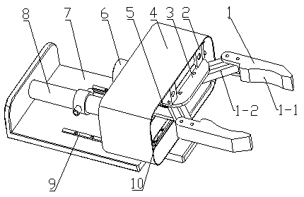
[0018] A tool-changing mechanical gripper for a shield machine inserting single hob; it includes two parts: a gripper body module and a path drive module.

[0019] The jaw body module includes a jaw 1, a worm gear mechanism 5, a hydraulic motor 6 and a jaw frame 3; the middle part of the jaw 1 is connected to the jaw frame 3 through pins, and the rear end of the jaw 1 is connected Worm gear mechanism 5; one end of the worm gear mechanism 5 is also connected to a hydraulic motor 6; the hydraulic motor 6 is fixedly connected to the jaw frame 3 through the hydraulic motor base; the jaw body module is arranged in the jaw box body 4 inside.

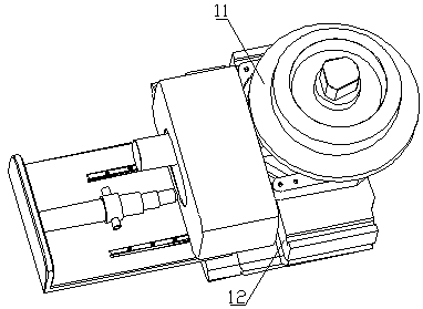
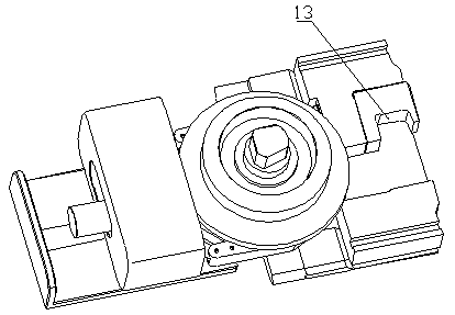
[0020] The path driving module includes a hydraulic cylinder 2, a linear guide rail 10. Gripper box 4. Linear guide rail 9. Multi-stage hydraulic cylinder 8 and jaw platform 7.

[0021] The hydraulic cylinder 2...


PUM


Abstract

The invention belongs to the mechanical field of shield machines, and relates to a cutter-changing machine clamping claw for a single hob of a shield machine. The cutter-changing machine clamping clawfor the single hob of the shield machine comprises a clamping claw body module and a path driving module. The clamping claw body module comprises a clamping claw, a worm wheel and worm rod mechanism,a hydraulic motor and a clamping claw frame. The path driving module comprises a hydraulic cylinder, a linear guide rail I, a clamping claw box body, a linear guide rail II, a multi-stage hydraulic cylinder and a clamping claw platform. The multi-stage hydraulic cylinder is matched with the linear guide rail II to control the advance and retreat of the whole claw clamping box body. The hydrauliccylinder is matched with the linear guide rail I to control the lateral movement of the clamping claw frame. The worm wheel and worm rod mechanism controls the tightening and opening of the clamping claw. The machine clamping claw has large bearing capacity, moderate volume, simple movement track, convenient operation and high efficiency of removing the hob, and the replacement time of the hob isshortened.

Description

technical field [0001] The invention belongs to the mechanical field of shield tunneling machines, and relates to a hob cutter-changing mechanical gripper of a shield tunneling machine, in particular to a tool-changing mechanical gripper used for a single hob of a shield tunneling machine. Background technique [0002] Shield machines are widely used in underground rail transit, water pipelines, power tunnels and other projects, while shield machines with single-edged hobs are mainly used in rock tunnel excavation and other projects; long-term work will cause a certain degree of wear on the cutter , It is necessary to open the cabin regularly to check and replace the cutting tool. Due to the harsh working environment and high-pressure sealing, workers will have great difficulties and dangers in the tool changing operation, and the use of robots to replace hobs has attracted increasing attention. [0003] However, due to the large size and weight of the hob, the path of disas...

Claims


Application Information

Patent Timeline
Patent Type & Authority Applications(China)
IPC IPC(8): E21D9/08B25J15/08B25J9/14
CPCE21D9/08B25J9/14B25J15/08
Inventor 李庆党张东阳吕晓龙
Owner QINGDAO UNIV OF SCI & TECH
Why Eureka
Try Eureka