Metal hose flow characteristic testing device and method

A technology of metal hose and flow characteristics, which is applied in the testing of mechanical components, testing of machine/structural components, and measuring devices. Influence and affect the accuracy of test results, etc., to achieve the effect of controllable test conditions, simple composition, and improved work efficiency

Pending Publication Date: 2019-02-22
AEROSUN CORP
View PDF6 Cites 2 Cited by
  • Summary
  • Abstract
  • Description
  • Claims
  • Application Information

AI Technical Summary

Problems solved by technology

[0003] Conventional flow characteristic test equipment mainly uses flowmeters and differential pressure meters to measure flow and differential pressure. Since the temperature during the test is not regulated, the influence of temperature instability on the flow resistance of the metal hose system cannot be eliminated, and for For metal hoses of different specifications, it is necessary to manually select flow meters and differential pressure meters that match the range according to parameters such as diameter, wave pitch, wave height, wall thickness, and length. It will also affect the accuracy of the test results because the test results are close to the limit of the range

Method used


Image

  • Metal hose flow characteristic testing device and method
  • Metal hose flow characteristic testing device and method
  • Metal hose flow characteristic testing device and method

Examples


Embodiment 1

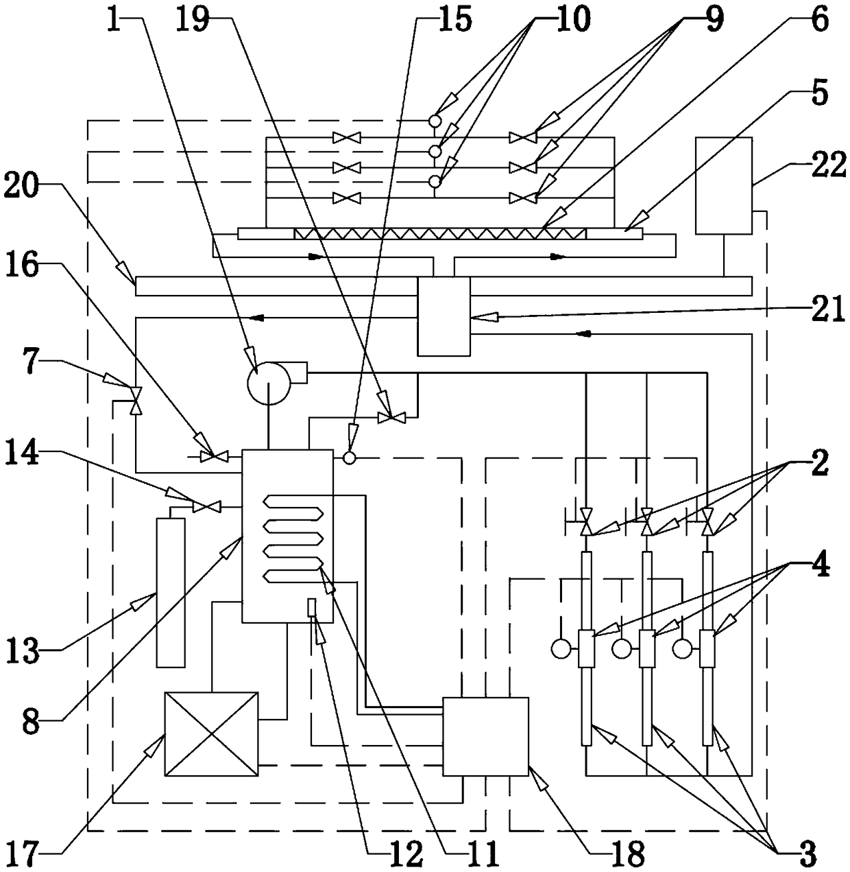
[0056] The metal hose flow characteristic test equipment of the present embodiment constitutes as figure 1 As shown, the two ends of the metal hose 6 to be tested are respectively connected with the front and rear pressure difference steady flow tubes 5, wherein the length of the front pressure difference steady flow tube is 10-12 times the diameter of the metal hose 6 to be tested, and the rear pressure difference The length of the differential steady flow tube is 5-8 times of the diameter of the metal hose 6 to be tested. The front and rear differential pressure stabilizing tubes 5 are respectively connected to two ends of three parallel differential pressure test pipelines with different diameters. Each differential pressure test pipeline is respectively connected in series with a differential pressure control valve 9 and a differential pressure sensor 10 . The rear differential pressure stabilizing pipe 5 is connected to the return port of the stabilizing water tank 8 thro...


PUM


Abstract

The invention relates to a metal hose flow characteristic testing device and method. Each of front and back pressure difference current stabilizing tubes of the device is communicated with the two ends of multiple parallel pressure difference testing pipes, the back pressure difference current stabilizing tube is connected to a pressure stabilizing water tank, an outlet of the pressure stabilizingwater tank is connected to multiple parallel flow testing pipes, and each flow testing pipe comprises front and back flow current stabilizing tubes; a heating device is installed in the pressure stabling water tank, and forms cooling circulation together with a cooling set; the signal output end of each of an upper pressure sensor, a lower temperature sensor, a pressure difference sensor and a flowmeter is connected with the controlled ends of a pressure regulator valve, the heating device and the cooling set via a control unit; a pressure difference and flow selected control output end of the control unit end is connected to the controlled end of a pressure difference selected control valve and a flow selected control valve; and the control unit includes an intelligent device and a display device. Thus, influence of temperature instability on flow resistance can be avoided, the proper control selective pipe can be selected automatically, an accurate test structure is obtained, and the working efficiency is improved.

Description

technical field [0001] The invention relates to flow characteristic testing equipment, in particular to a metal hose flow characteristic testing equipment, and also relates to a corresponding testing method, which belongs to the technical field of hydraulic equipment testing and metal hose performance testing. Background technique [0002] In hydraulic equipment testing and performance testing of high-pressure metal pipes, in addition to the conventional pressure-resistant and pressure-holding tests, in view of the flow resistance of metal hoses (metal bellows) in large-scale equipment systems has a special change rule, especially the flow stability The law of resistance characteristics under unsteady states and flow conditions has an important impact on the operating drive power of the entire system and the control of downstream pressure requirements of the system, so it is necessary to test the flow characteristics. [0003] Conventional flow characteristic test equipment ...

Claims


Application Information

Patent Timeline
Patent Type & Authority Applications(China)
IPC IPC(8): G01D21/02G01M13/00G08B19/00
CPCG08B19/00G01D21/02G01M13/00
Inventor 陈正标赵术伟陈为柱
Owner AEROSUN CORP
Why Eureka
Try Eureka