Windowless main amplification system for high power laser device

A laser device and windowless technology, which is applied in the direction of lasers, laser components, laser optical equipment, etc., can solve the problems of limiting the output capability of laser drivers, large energy flow, and adding optical elements, so as to improve beam quality and reduce optical elements , reduce the effect of B points

Active Publication Date: 2019-02-22
SHANGHAI INST OF OPTICS & FINE MECHANICS CHINESE ACAD OF SCI
View PDF9 Cites 0 Cited by
  • Summary
  • Abstract
  • Description
  • Claims
  • Application Information

AI Technical Summary

Problems solved by technology

Although the above measures finally meet the extremely stringent requirements of the main amplifier system of high-power devices, the use of window glass at both ends of the chip amplifier increases the use of optical components while achieving the internal clean environment of class 100. Part of the energy flow is larger, so the influence of the B integral is more significant, limiting the output capability of the laser driver

Method used


Image

  • Windowless main amplification system for high power laser device
  • Windowless main amplification system for high power laser device
  • Windowless main amplification system for high power laser device

Examples


Embodiment 1

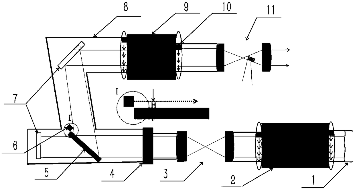
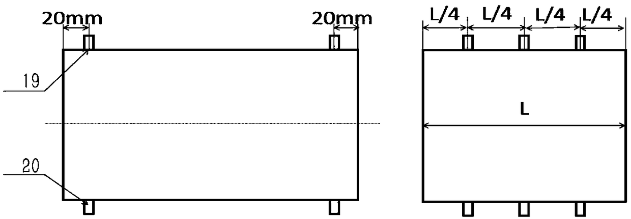
[0018] refer to figure 1 , figure 1 It is a structural schematic diagram of Embodiment 1 of the windowless main amplification system of the high-power laser device of the present invention. It can be seen from the figure that the windowless main amplification system of the high-power laser device of the present invention includes a deformable mirror 1, a main amplifier 2, a first Spatial filter 3, plasma switch 4, polarizer 5, mirror 7, booster amplifier 9 and second spatial filter 11; in deformable mirror 1, main amplifier 2, first spatial filter 3, plasma switch 4 , polarizer 5, reflector 7, booster amplifier 9 and the second spatial filter 11 are airtightly connected by light pipe 8, and the two ends of the main amplifier 2 and the booster amplifier 9 are respectively A flow field barrier 10 is set, an air knife A6 is set on the edge of the polarizer 5, and the light duct 8 is provided with an air inlet 19 and an air outlet 20, and the air inlet 19 is connected with the in...

Embodiment 2

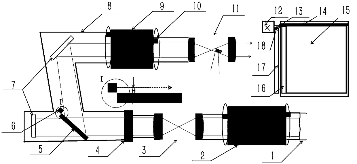
[0021] refer to image 3 , image 3 It is a structural schematic diagram of Embodiment 2 of the windowless main amplification system of the high-power laser device of the present invention; it can be seen from the figure that the windowless main amplification system of the high-power laser device of the present invention includes a deformable mirror 1, a main amplifier 2, a first Spatial filter 3, plasma switch 4, polarization 5, mirror 7, booster amplifier 9 and second spatial filter 11, characterized in that deformable mirror 1, main amplifier 2, first spatial filter 3, plasma Switches, polarizers 5, reflectors, booster amplifiers 9 and second spatial filters 11 are airtightly connected by light pipes 8, and the two ends of the main amplifier 2 and booster amplifiers 9 are respectively provided with flow field barriers Object 10, an air knife A 6 is arranged on the edge of the polarizer 5 . The gas source is dry and clean nitrogen. The automatic opening and closing mechan...


PUM


Abstract

A windowless main amplification system for a high power laser device comprises a deformable mirror, a main amplifier, a first spatial filter, a polarizer, a reflector, a booster amplifier and a secondspatial filter, which are sequentially disposed along an optical path; The system is characterized in that the deformable mirror, the main amplifier, the first spatial filter, the polarizer, the reflector, the booster amplifier and the second spatial filter are closely connected with each other by a light pipe; external pollutants are isolated and deposited on the surface of components; flow field obstacles are respectively disposed on two ends of the main amplifier and the booster amplifier; airflow exchange between the light pipe and the main amplifier and the booster amplifier is blocked;an air knife A is disposed at the edge of the polarizer; and natural dust fall is isolated. The system has the advantages of ingenious design, and simple and easy operation, ensures the cleanliness ofthe main amplification system, does not bring secondary pollution, simultaneously helps to reduce B integral, makes the beam quality of a laser system improve, and helps to improve the output capability of the laser device.

Description

technical field [0001] The invention relates to a high-power laser device, in particular to a windowless main amplification system of a high-power laser device. Background technique [0002] With the development of high-energy density physics and fusion research, higher and higher requirements are put forward for high-power laser systems. For example, the output energy of NIF in the United States can reach the MJ level. The main amplifier system is composed of optical components such as chip amplifiers, spatial filters, reflectors, and polarizers. It is the key link in the energy amplification of high-power laser devices, providing more than 99% of the energy. Strict requirements, such as maintaining a class 100 clean working environment for chip amplifiers, maintaining a class 10,000 working environment for devices, etc. At present, the chip amplifier achieves a class 100 clean working environment through sealing the window glass at both ends, filling and discharging dry a...

Claims


Application Information

Patent Timeline
IPC IPC(8): H01S3/00
CPCH01S3/005H01S3/0071
Inventor 王冰艳李养帅张攀政周申蕾马伟新朱俭朱健强刘志刚夏志强张严峰
Owner SHANGHAI INST OF OPTICS & FINE MECHANICS CHINESE ACAD OF SCI
Why Eureka
Try Eureka