Chemical-fiber-silk rapid cooling equipment

A technology of rapid cooling and chemical fiber yarn, applied in the field of chemical fiber yarn, can solve the problems of low resource utilization rate, low cooling rate, long cooling time, etc., and achieve the effect of improving utilization rate, improving heat dissipation rate, and improving effect

Inactive Publication Date: 2019-02-26
长兴一盛纺织有限公司
View PDF1 Cites 4 Cited by
  • Summary
  • Abstract
  • Description
  • Claims
  • Application Information

AI Technical Summary

Problems solved by technology

[0003] The present invention provides a kind of rapid cooling equipment for chemical fiber filaments, which can effectively solve the problems of low cooling rate, long cooling time, low resource utilization rate and high cost of the common cooling device proposed in the above-mentioned background technology.

Method used


Image

  • Chemical-fiber-silk rapid cooling equipment
  • Chemical-fiber-silk rapid cooling equipment
  • Chemical-fiber-silk rapid cooling equipment

Examples


Embodiment Construction

[0022] The preferred embodiments of the present invention will be described below in conjunction with the accompanying drawings. It should be understood that the preferred embodiments described here are only used to illustrate and explain the present invention, and are not intended to limit the present invention.

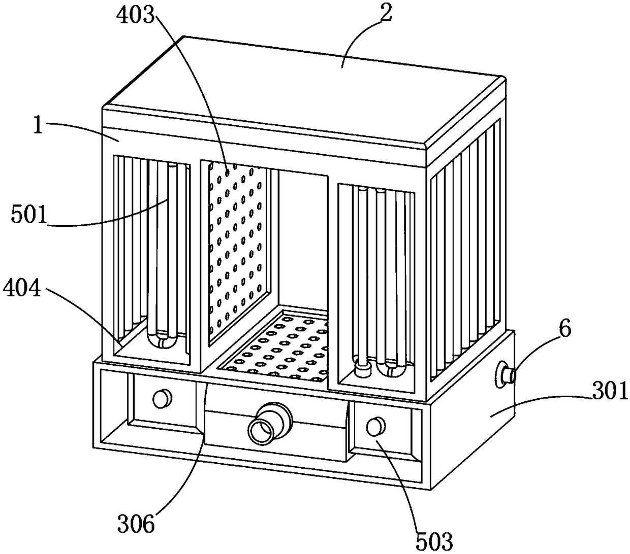
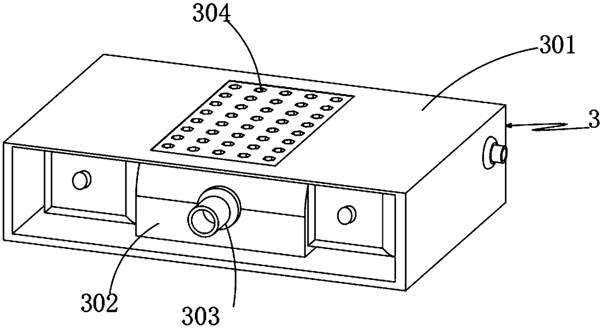
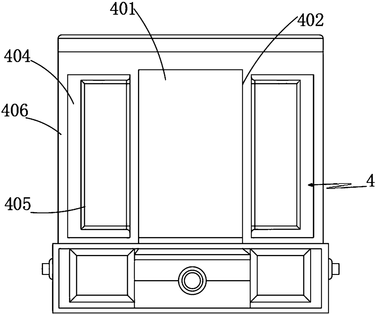
[0023] Example: such as Figure 1-4 As shown, the present invention provides a technical solution, a chemical fiber filament rapid cooling equipment, including a cooling box 1, in order to facilitate the maintenance of the cooling box 1, the top of the cooling box 1 is equipped with a box cover 2, and the inside of the cooling box 1 is installed The air-cooled assembly 4, the air-cooled assembly 4 includes an air flow channel 401, a partition plate 402, a porous rectifying plate 403, a cooling chamber 404, a chemical fiber storage box 405 and an air outlet 406, and an air flow channel 401 is provided at the center of the cooling box 1, Both ends of the air flow chan...


PUM


Abstract

The invention discloses chemical-fiber-silk rapid cooling equipment. The chemical-fiber-silk rapid cooling equipment comprises a cooling box, an air cooling assembly is installed inside the cooling box, and a water-cooling assisting assembly is installed on one side of the air cooling assembly. The chemical-fiber-silk rapid cooling equipment is scientific and reasonable in structure and safe and convenient to use; the equipment is provided with the air cooling assembly, through the effects of an airflow channel, cooling chambers, chemical-fiber-silk storage boxes and air outlets, cooling air blows to chemical fiber silk, and is dispensed externally through the air outlets, and therefore the temperature on the surface of the chemical fiber silk is reduced in a flowing manner; through effects of partition plates and porous current plates, cooling air is conveniently rectified and evenly flows, and the cooling effect of the chemical fiber silk is improved; the equipment is provided with the water-cooling assisting assembly, through effects of water-cooling pipes, water storage tanks and heat guiding plates, cooling water is conveniently used for assisting the chemical fiber silk in heat dissipation, and therefore the heat dissipation rate of the chemical fiber silk is increased; through effects of grooves and water outlet pipes, wind power at the air outlets conveniently flows totake away heat in water of the water outlet pipes, and the resource utilization rate is increased.

Description

technical field [0001] The invention relates to the technical field of chemical fiber filaments, in particular to a rapid cooling device for chemical fiber filaments. Background technique [0002] Chemical fiber yarn is made of natural polymer compound or artificially synthesized polymer compound as raw material. It is a fiber with textile properties obtained through the preparation of spinning dope, spinning and post-treatment. In the production process of chemical fiber yarn, chemical fiber yarn needs to be For cooling and forming, a new type of cooler for chemical fiber equipment is involved in the patent 201720737469.2, in which a cooling wheel is provided in the cooler and a spiral groove is provided on the surface, so that the chemical fiber is supported during the cooling process and the chemical fiber is improved. Structural performance, through the use of automatic control devices, it is convenient for the cooler to automatically adjust the cooling fan, but the cool...

Claims


Application Information

Patent Timeline
Patent Type & Authority Applications(China)
IPC IPC(8): D01D5/088
CPCD01D5/088
Inventor 张辰罗冬英
Owner 长兴一盛纺织有限公司
Why Eureka
Try Eureka