
Modified calculation method for energy saving effect of low-pressure economizer

A technology of low-pressure economizer and energy-saving effect, applied in the direction of calculation, computer-aided design, instrument, etc., can solve the problems of quantitative analysis, evaluation of energy-saving effect of low-pressure economizer, deviation of operating parameters from design conditions, etc.

Active Publication Date: 2019-02-26
HUADIAN ELECTRIC POWER SCI INST CO LTD
View PDF5 Cites 8 Cited by
  • Summary
  • Abstract
  • Description
  • Claims
  • Application Information

AI Technical Summary

Problems solved by technology

However, the calculated energy-saving effect of the low-pressure economizer in the actual project is far lower than the design value, mainly because the operating conditions and the operating parameters of the smoke side and water side deviate from the design conditions.
Although previous studies have qualitatively analyzed the relationship between the energy-saving effect of low-pressure economizers and operating parameters, such as the Chinese patent with the publication date of February 16, 2018, the publication number is CN107703181A, and the publication date is April 13, 2018. No. CN107909309A Chinese patent; but without in-depth quantitative analysis of the deviation between the actual energy-saving effect and the design value, it is impossible to evaluate the energy-saving effect of the low-pressure economizer, and put forward some suggestions for the operation mode of the low-pressure economizer Targeted optimization measures

Method used


Image

  • Modified calculation method for energy saving effect of low-pressure economizer
  • Modified calculation method for energy saving effect of low-pressure economizer
  • Modified calculation method for energy saving effect of low-pressure economizer

Examples


Embodiment Construction

[0068] The present invention will be further described in detail below in conjunction with the accompanying drawings and examples. The following examples are explanations of the present invention and the present invention is not limited to the following examples.

[0069] Example.

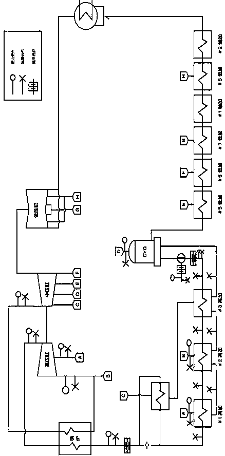
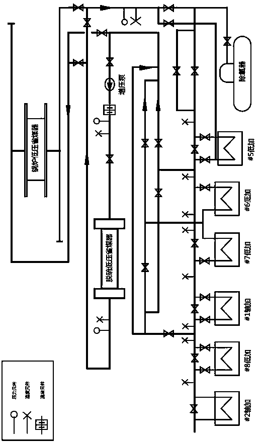
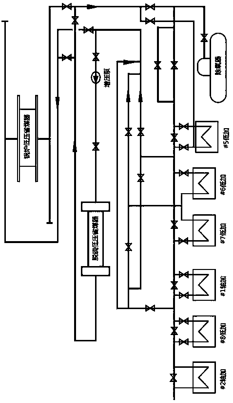
[0070] The correction calculation method for the energy-saving effect of the low-pressure economizer in this embodiment includes the following steps:

[0071] Step 1: Arrange several pressure, temperature and flow measuring points in the thermal system of the steam turbine unit.

[0072] Step 2: Arrange several pressure, temperature and flow measuring points on the water side and flue gas side of the low-pressure economizer.

[0073] Step 3: Carry out the thermal performance test of the steam turbine under the two operating conditions of the low-pressure economizer in operation and out of operation, calculate the test heat consumption rate of the steam turbine unit, and calculate the heat consumpt...


PUM


Abstract

The invention relates to a correction calculation method for energy-saving effect of a low-pressure economizer, belonging to the field of power generation. At present, there is no deep quantitative analysis of the deviation between the actual energy-saving effect and the design value. The invention comprises the following steps: 1, arranging a plurality of pressure, temperature and flow measuringpoints in the thermodynamic system of a steam turbine unit; 2, arranging a number of pressure, temperature and flow measuring points on the water side and flue gas side of the low-pressure economizer;3, carrying out thermodynamic performance tests of a steam turbine under two operating conditions of commissioning and shutdown of that low-pressure economizer, and obtain the energy-saving effect ofthe low-pressure economizer; 4. calcualting the heat transfer coefficient, logarithmic average temperature difference and heat transfer of low-pressure economizer under the test condition; 5, calculating the heat exchange of the corrected low-pressure economizer; 6, The energy-saving effect of the low-pressure economizer is obtained after the operation parameters are corrected. The invention canjudge the energy-saving effect of the low-pressure economizer, and can obtain the energy-saving effect of the corrected low-pressure economizer.

Description

technical field [0001] The invention relates to a correction calculation method for the energy-saving effect of a low-pressure economizer, in particular to a correction calculation method for the energy-saving effect after a low-pressure economizer is installed in the tail flue of a coal-fired boiler, and belongs to the field of power generation. Background technique [0002] Domestic power plant boilers generally have the problem of high exhaust gas temperature. Severely overheated exhaust gas temperature not only affects the thermal economy of the power plant, but also affects the safe operation of the air preheater. Therefore, reducing the exhaust gas temperature has important practical significance for saving energy, reducing consumption, and improving the safety of boiler operation. At present, the boiler flue gas waste heat recovery scheme mainly includes the scheme of using low-pressure economizer system to heat condensate water, the scheme of using exhaust waste heat...

Claims


Application Information

Patent Timeline
IPC IPC(8): G06F17/50
CPCG06F2119/08G06F30/20
Inventor 王学栋刘传玲闫玉峰宋昂张其龙柳明辉朱同兵赵玉柱王学同
Owner HUADIAN ELECTRIC POWER SCI INST CO LTD
Learn More