Dual-frequency antenna

A dual-frequency antenna and antenna technology, which is applied to antennas, antenna components, antenna grounding devices, etc., can solve the problems of beam distortion of the transmitting and receiving antenna pattern, asymmetric installation position, and antenna performance degradation, and achieve pattern symmetry and achieve The effect of impedance matching

Active Publication Date: 2019-02-26
HUBEI SANJIANG SPACE XIANFENG ELECTRONICS&INFORMATION CO LTD
View PDF11 Cites 3 Cited by
  • Summary
  • Abstract
  • Description
  • Claims
  • Application Information

AI Technical Summary

Problems solved by technology

[0003] Due to the requirements of system integration, the design of the transceiver antennas used in communication and radar systems requires integration and simultaneous operation of transceiver frequency division. In order to ensure the normal operation of the communication system, high isolation between transceiver antennas and symmetrical beams of transceiver antennas are required. Difficult to meet the above requirements at the same time
[0004] At present, the combination-type transceiver antenna can adopt the form of stacked coupling feeding. The pattern beams of multiple resonant frequency points of the antenna are basically symmetrical and meet the requirements. However, since the working mode of the stacked antenna is the upper radiation patch The lower radiating patch works as the ground terminal of the upper radiating patch. If the dual-port design is selected, the isolation of the antenna is low because the interval between the two resonant frequencies of the upper radiating patch and the lower radiating patch is not wide enough. Mutual influence cannot meet the isolation requirements of the transceiver antenna; if a single-port design is selected, the design of the transceiver circuit will be more complicated and difficult due to the need for simultaneous operation of transceivers. At the same time, the upper and lower radiation patches of the stacked antenna are limited by the operating frequency It is difficult to realize; adopting the method of separating the transmitting and receiving array elements under the local interface, setting the appropriate array element spacing and adopting dual-port feeding can meet the isolation requirements of the transmitting and receiving antennas. However, due to the limited interface, the transmitting and receiving antennas are separated. The layout opening will lead to relative asymmetry in the installation position, resulting in beam distortion and asymmetry in the pattern of the transmitting and receiving antenna, thereby degrading the performance of the antenna

Method used


Image

  • Dual-frequency antenna
  • Dual-frequency antenna
  • Dual-frequency antenna

Examples


Embodiment Construction

[0032] In order to make the object, technical solution and advantages of the present invention clearer, the present invention will be further described in detail below in conjunction with the accompanying drawings and embodiments. It should be understood that the specific embodiments described here are only used to explain the present invention, not to limit the present invention.

[0033] In addition, the technical features involved in the various embodiments of the present invention described below can be combined with each other as long as they do not constitute a conflict with each other.

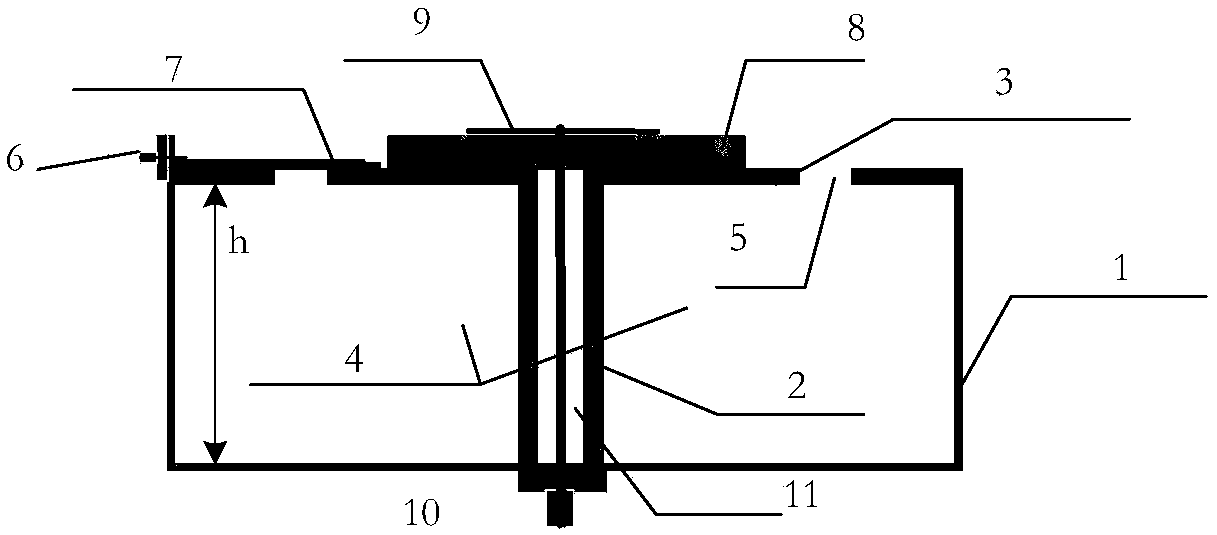
[0034] figure 1 It is a schematic structural diagram of a dual-frequency antenna in a preferred embodiment of the present invention. Such as figure 1 As shown in , the dual-frequency antenna includes a cavity-backed shell 1, a support rod 2, a mounting plate 3, an air-backed cavity 4, a radiation slot 5, a first feeding port 6, a feeding printed line 7, a radiation substrate 8, The r...


PUM


Abstract

The invention discloses a dual-frequency antenna which comprises a slot vibrator antenna and a microstrip antenna, wherein the slot vibrator antenna and the microstrip antenna are arranged in combination with each other. The slot vibrator antenna is in a cylindrical symmetrical structure which is composed of a back cavity casing body with an air back cavity and is centered on a support rod. An annular radiation slot is arranged around the center point at the upper part of the back cavity casing body. The microstrip antenna is in a structure with a support rod. A mounting plate and a radiationactinal surface are arranged at the upper part of the support rod. A coaxial feeding medium is arranged and filled in the hollow cavity of the support rod. Through the study and design of the structure and arrangement manner of the key components of the dual-frequency antenna, such as the radiation slot, the radiation actinal surface and the feeding, the structure of the dual-frequency antenna with the combined microstrip antenna and slot vibrator antenna is symmetrical. The dual-frequency antenna has the advantages of symmetrical directional diagram, non-distortion beam and high isolation.

Description

technical field [0001] The invention belongs to the technical field of antennas, and in particular relates to a dual-frequency antenna. Background technique [0002] In principle, communication and radar electronic systems are the process of transmitting and receiving electromagnetic waves, and their structures include antennas, transmitters, receivers, signal processors, etc. Among them, the working principle of the transceiver antenna is: when a high-frequency current is passed through the conductor, an electric field and a magnetic field will be generated in the surrounding space. After the electromagnetic wave is radiated from the transmitting antenna, it propagates in all directions. If a symmetrical vibrator is set in the direction of electromagnetic wave propagation, then under the action of the electromagnetic wave, an induced electromotive force will be generated on the antenna vibrator. At this time, the antenna is connected to the receiving device, and a high-fre...

Claims


Application Information

Patent Timeline
Patent Type & Authority Applications(China)
IPC IPC(8): H01Q1/36H01Q1/48H01Q1/50H01Q1/12H01Q5/20
CPCH01Q1/1207H01Q1/36H01Q1/48H01Q1/50H01Q5/20
Inventor 邹远磊邱薇曹轲
Owner HUBEI SANJIANG SPACE XIANFENG ELECTRONICS&INFORMATION CO LTD
Why Eureka
Try Eureka