A broadband high-efficiency antenna unit, series-parallel feed sub-array and phased array

An antenna unit, high-efficiency technology, applied to antenna arrays, individually powered antenna arrays, antennas, etc., can solve problems such as inability to achieve low-energy signal coverage, inability to ensure normal signal transmission, and narrow array beam widths. and the effect of small weight, low loss, and improved isolation

Active Publication Date: 2022-07-26
SOUTH CHINA UNIV OF TECH
View PDF13 Cites 0 Cited by
  • Summary
  • Abstract
  • Description
  • Claims
  • Application Information

AI Technical Summary

Problems solved by technology

However, in the millimeter wave frequency band, the transmission loss of electromagnetic waves in space will increase significantly. Using a single or a small number of antenna units, the gain is low, and the normal transmission of signals cannot be guaranteed. The antenna array has high gain and can achieve long-distance signal transmission; but the array exists Narrow beam width and low radiation efficiency make it impossible to achieve low energy consumption and wide-angle signal coverage

Method used


Image

  • A broadband high-efficiency antenna unit, series-parallel feed sub-array and phased array
  • A broadband high-efficiency antenna unit, series-parallel feed sub-array and phased array
  • A broadband high-efficiency antenna unit, series-parallel feed sub-array and phased array

Examples


Embodiment 1

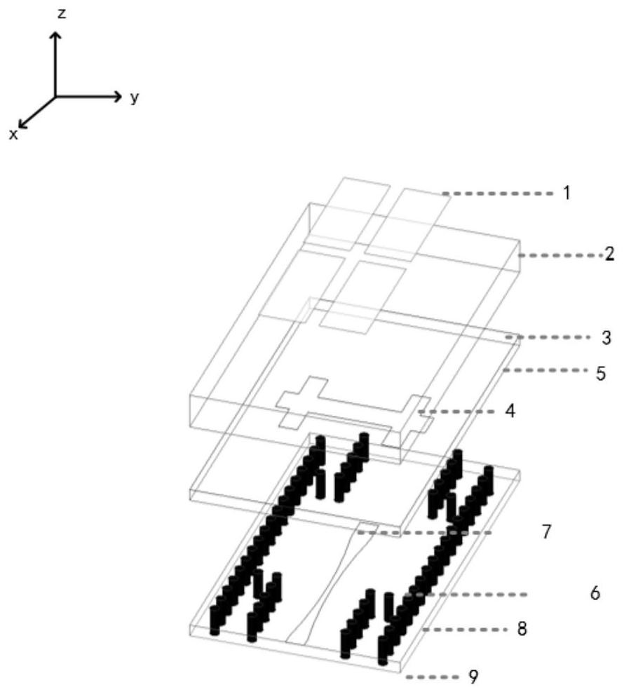
[0041] like figure 1 As shown, a broadband high-efficiency antenna unit adopts a multi-layer PCB process, and the entire antenna uses Roger5880 as a dielectric substrate. It includes a first dielectric substrate 2 , a first metal floor 3 , a second dielectric substrate 5 , a third dielectric substrate 8 and a second metal floor 9 , which are arranged in sequence from top to bottom. The upper surface of the first dielectric substrate is provided In the metasurface structure 1 , a feeding slot 4 is etched on the first metal floor 3 , and a strip-shaped feeding line 7 is arranged between the third dielectric substrate 8 and the second dielectric substrate 5 .

[0042] As the radiation part of the antenna: the metasurface structure 1 is composed of M×N metasurface units arranged in a centrosymmetric periodic arrangement, and the metasurface structure in this embodiment 1 is constituted by 2×2 metasurface units arranged in a centrosymmetric periodic arrangement. The metasurface un...

Embodiment 2

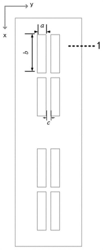
[0049] As shown in Fig. 3(a), Fig. 3(b) and Fig. 3(c), a series-parallel feed sub-array includes two mirror-symmetric series-connected sub-arrays, and the two series-connected sub-arrays are spliced ​​according to the mirror symmetry axis , the series sub-array D is formed by a plurality of broadband high-efficiency antenna elements as described in Embodiment 1 arranged in series along the sub-array direction.

[0050] As shown in Figure 2(a), Figure 2(b) and Figure 2(c), the series sub-array D consists of two broadband high-efficiency antenna units extended in the direction of the sub-array, and the two feeding slots are symmetrical.

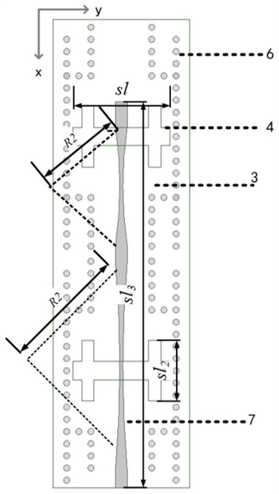
[0051]Each broadband high-efficiency antenna unit is further provided with a fourth dielectric substrate 11 and a third metal floor 12 below the second metal floor 9 , and the first coupling slot 10 and the third metal floor 12 are etched at the center of the second metal plate 9 . The second coupling slot 13 is etched, and the second coupling ...

Embodiment 3

[0057] like Figure 4 As shown, a phased array is composed of several serial-parallel feed sub-arrays arranged periodically along the vertical direction of the sub-array. Metal phase perturbation branches 15 are loaded around the head and tail ends of the strip feed lines 7 of the sub-arrays, so as to improve the isolation between adjacent series-parallel feed sub-arrays.

[0058] The metal phase perturbation branch is arranged on the same layer or different layer as the strip feeder to improve the isolation of adjacent series-parallel feed sub-arrays, and the metal phase perturbation branch of the phased array is symmetrical according to the mirror symmetry axis.

[0059] The scanning range of the phased array is determined by the distance between adjacent serial-parallel sub-arrays. The smaller the distance, the larger the scanning range. Generally less than half a wavelength, so the size of the broadband high-efficiency antenna element along the beam scanning direction sho...


PUM


Abstract

The invention discloses a broadband high-efficiency antenna unit, a series-parallel feed sub-array and a phased array. The antenna unit includes a first dielectric substrate, a first metal floor, a second dielectric substrate, a third dielectric substrate and a second dielectric substrate arranged in sequence. A metal floor, the upper surface of the first dielectric substrate is provided with a metasurface structure, a feeding gap is etched on the first metal floor, and a strip-shaped feeding line is arranged between the first metal floor and the second dielectric substrate. A serial-parallel feed sub-array includes two mirror-symmetric serial sub-arrays, the two serial sub-arrays are spliced ​​according to the mirror symmetry axis, and a phased array includes several serial-parallel feed sub-arrays along the vertical direction of the sub-arrays Arranged periodically, the invention is easy to process, low in cost and low in profile, suitable for the design of a planar antenna array and applied to mass production.

Description

technical field [0001] The invention relates to the field of communications, in particular to a broadband high-efficiency antenna unit, a serial-parallel feed sub-array and a phased array. Background technique [0002] Phased array antennas have a wide range of applications in the military and communications fields. In early radar systems, the beam direction of the array antenna was fixed, and the beam direction needs to be controlled by mechanical scanning. Compared with the traditional fixed beam array, the phased array antenna can quickly and accurately It can control the beam to perform inertia-free scanning, and realize the function of searching and tracking multiple targets at the same time in the designated space. Phased array antennas were originally used in military radars to observe and track airframe targets in a wide range of space. With the development of wireless communication technology, phased array technology has also begun to be used in civilian products, ...

Claims


Application Information

Patent Timeline
Patent Type & Authority Patents(China)
IPC IPC(8): H01Q1/38H01Q1/48H01Q1/50H01Q3/30H01Q15/00H01Q21/00H01Q21/06
CPCH01Q1/38H01Q1/48H01Q1/50H01Q15/0086H01Q21/061H01Q21/0075H01Q3/30
Inventor 杨琬琛肖峰车文荃薛泉刘宇济
Owner SOUTH CHINA UNIV OF TECH
Why Eureka
Try Eureka