
Straight seam automatic welding device

An automatic welding and straight seam technology, which is applied in the direction of auxiliary devices, welding equipment, auxiliary welding equipment, etc., can solve the problems of cumbersome operation, moving position, weak welding place, and affecting the quality of waste incinerator, so as to achieve simple operation and improve welding efficiency. quality effect

Active Publication Date: 2019-03-01
CHONGQING SHANGZE ELECTROMECHANICAL
View PDF6 Cites 2 Cited by
  • Summary
  • Abstract
  • Description
  • Claims
  • Application Information

AI Technical Summary

Problems solved by technology

When welding, it is necessary to ensure that the positions to be welded of the two workpieces to be welded coincide with the moving route of the welding torch. This requires people to constantly adjust the positions of the two workpieces to be welded when placing the workpieces to be welded so that the two workpieces to be welded The alignment end of the workpiece coincides with the moving position of the welding torch, which is not only cumbersome to operate, but also easily leads to a deviation between the alignment position of the two workpieces to be welded and the moving position of the welding torch during manual operation, resulting in weak welding and affecting the quality of the waste incinerator

Method used


Image

  • Straight seam automatic welding device
  • Straight seam automatic welding device
  • Straight seam automatic welding device

Examples


Embodiment Construction

[0021] The following is further described in detail through specific implementation methods:

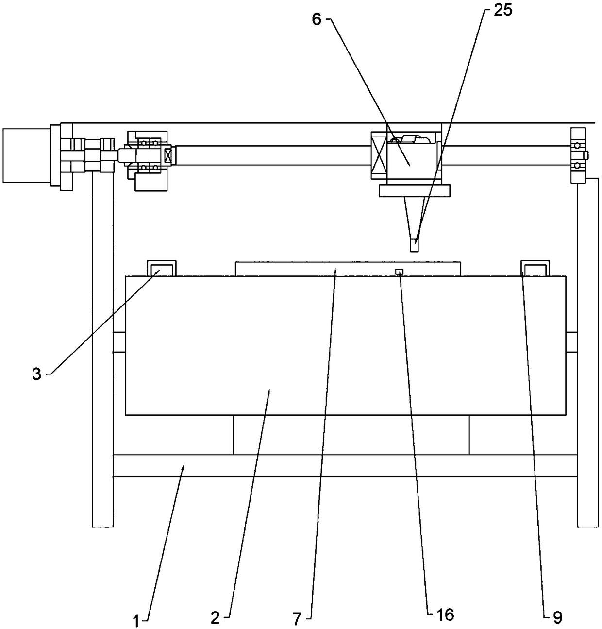
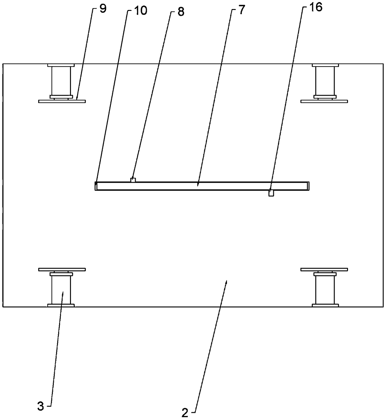
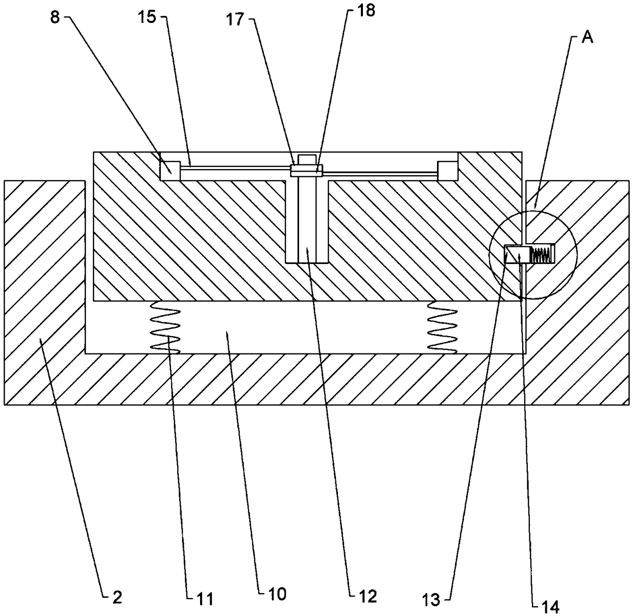
[0022] The reference signs in the drawings of the description include: frame 1, workbench 2, cylinder 3, nut seat 6, positioning plate 7, first slide bar 8, push plate 9, strip groove 10, tension spring 11, column 12 , limit groove 13, inclined block 14, connecting rod 15, second slide bar 16, first ring 17, second ring 18, groove 19, electromagnet 20, compression spring 21, permanent magnet 22, insulating layer 23. Conductive segment 24, welding torch 25.

[0023] The embodiment is basically as attached figure 1 Shown: a straight seam automatic welding device, including a frame 1, a welding structure and a positioning plate 7. The upper part of the frame 1 is provided with a workbench 2, and the welding structure is located at the upper end of the frame 1; the welding structure includes a welding torch 25 and a drive unit for driving the welding torch 25 to move horizontally. In t...


PUM


Abstract

The invention belongs to the field of welding devices, and particularly discloses a straight seam automatic welding device. The straight seam automatic welding device comprises a machine frame and a welding structure; the machine frame is provided with a workbench; the middle of the workbench is provided with a strip-shaped groove, the strip-shaped groove coincides with the moving direction of a welding gun, and a positioning plate is located in the strip-shaped groove and can slide up and down along the strip-shaped groove; the two sides of the workbench are provided with pushing mechanisms correspondingly; two side parts of the positioning plate are provided with slide grooves, and each slide groove is internally and slidably connected with a slide rod; the positioning plate is providedwith a cavity, and a vertical column is arranged in the cavity; the upper portion of the vertical column is rotationally connected with an electro-conductive first ring and an electro-conductive second electro-conductive; the slide rods are connected with the first ring / the second ring through connection rods; the surfaces, abutting against each other, of the first ring and the second ring are provided with insulating layers, and the insulating layers of the first ring and the second ring are provided with electro-conductive sections; and the workbench is internally provided with a control structure for controlling the positioning plate to move downwards, and the first ring and the second ring are located in a circuit of the control structure. The straight seam automatic welding device canachieve automatic aligning during welding, and manual operation is reduced.

Description

technical field [0001] The invention belongs to the field of welding devices and specifically discloses a straight seam automatic welding device. Background technique [0002] The garbage incinerator is a device for incinerating garbage. The garbage burns in the furnace and becomes waste gas, which enters the secondary combustion chamber, burns completely under the forced combustion of the burner, and then enters the spray dust collector. After dust removal, it is discharged into the atmosphere through the chimney . The volume of garbage incinerators is generally very large, and when making garbage incinerators, many metal plates are welded together. In order to reduce workers' labor and improve welding efficiency, straight seam welding devices are now mostly used to weld large plates. [0003] Straight seam welding device, also called straight seam welding machine, is an automatic welding equipment for straight seam welding of workpieces through automation and mechanizati...

Claims


Application Information

Patent Timeline
IPC IPC(8): B23K37/02B23K37/00B23K37/04
CPCB23K37/00B23K37/0211B23K37/0426
Inventor 黄云凡
Owner CHONGQING SHANGZE ELECTROMECHANICAL
Learn More