Viaduct structure

A technology for viaducts and bridge piers, which is applied in the directions of superstructure sub-assemblies, connections between superstructure sub-assemblies, bridge parts, etc. The effect of handling and assembly, maintaining structural integrity, and short construction cycle

Inactive Publication Date: 2019-03-01
张跃
View PDF7 Cites 9 Cited by
  • Summary
  • Abstract
  • Description
  • Claims
  • Application Information

AI Technical Summary

Problems solved by technology

[0002] The existing viaducts are all made of concrete, which mainly have the following defects: first, the construction period is long; second, it is not easy to transport materials; third, the weight is heavy, it is difficult to carry and lift, and it is time-consuming and laborious; fourth, once the bridge is damaged , not easy to repair; fifth, poor vibration isolation performance; fifth, loud noise

Method used


Image

  • Viaduct structure
  • Viaduct structure
  • Viaduct structure

Examples


Embodiment 1

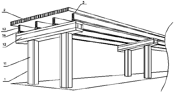
[0052] like figure 1 Shown: a viaduct structure, including a bridge deck 3 and a support body 1 for supporting the bridge deck 2 . Wherein, the supporting body 1 includes a bridge pier 11, a cover beam 12 and a support beam 13, the cover beam 12 is arranged on the bridge pier 11, the support beam 13 spans between a plurality of cover beams 12 through a support 14, and the bridge deck 3 is connected to the support Beam 13 on.

[0053] The piers 11 , cover beams 12 , support beams 13 and bridge deck 3 of this embodiment are all made of metal plates 2 . Wherein, both the support beam 13 and the bridge deck 3 are spliced ​​by a plurality of metal plates 2, and the number of metal plates 2 depends on the length of the bridge. Both the pier 11 and the cover beam 11 are spliced ​​by four metal plates 2 to form a columnar structure.

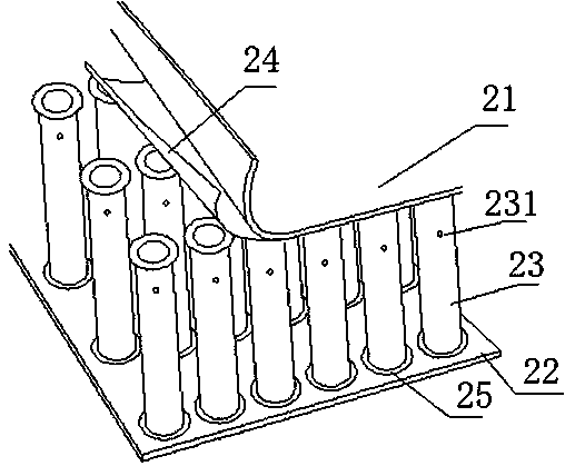
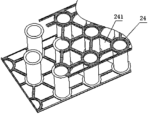
[0054] like figure 2 and image 3 As shown: in this embodiment, the metal plate 2 includes a first panel 21, a second panel 22 and a plurality of ...

Embodiment 2

[0064] like Figure 5 Shown: The difference with Embodiment 1 is that the bridge deck is an arc structure, and its first panel 21' and second panel 22' are curved panels. The two ends of the hollow pipe 23' are vertically connected with the contact surface of the panel. The linetype of curved panels is arc. A plurality of hollow tubes 23' are arranged at intervals, and the axis of each hollow tube 23' is perpendicular to the tangent line of the corresponding arc-shaped contact surface. In this way, the connection strength between the hollow tube 23' and the panel can be enhanced, and the occurrence of hollow tubes can be avoided. Many positions are not welded, or gaps or voids are generated, resulting in uneven brazing. This solution can greatly improve the overall strength and quality.

[0065] The first panel 21' and the second panel 22' have the same curvature.

[0066] Other structures are with embodiment 1.

Embodiment 3

[0068] like Image 6 Shown: the difference with embodiment 1 is that the bridge deck is an arc structure, and its first panel 21 " is an arc-shaped curved panel, and the second panel 22 " is a plane panel, and the flanging at one end of the hollow tube 23 " and The plane boards are parallel, and the flanging at the other end is an inclined plane, and the inclined plane is parallel to the contact surface of the curved boards, so that when the hollow tube is connected with the two boards, there will be no gap.

[0069] Other structures are with embodiment 1.


PUM


Abstract

A viaduct structure comprises a deck and a supporting body used for supporting the deck. The viaduct structure is characterized in that the deck and / or the supporting body is made of a metal plate; the metal plate comprises a first panel, a second panel and multiple hollow pipes, wherein the multiple hollow pipes are arranged between the first panel and the second panel; brazing layers are arranged between the hollow pipe and the first panel and between the hollow pipe and the second panels; and a turned-up edge is arranged at at least one end of each hollow pipe. The viaduct structure has theadvantages of light deadweight, high strength, stable structure, high pressure bearing capacity, sound insulation and noise reduction, high temperature resistance, vibration resistance, long servicelife and the like, and the viaduct structure can also be conveyed and spliced.

Description

technical field [0001] The invention relates to the technical field of bridges, in particular to a viaduct structure. Background technique [0002] The existing viaducts are all made of concrete, which mainly have the following defects: first, the construction period is long; second, it is not easy to transport materials; third, the weight is heavy, it is difficult to carry and lift, and it is time-consuming and laborious; fourth, once the bridge is damaged , not easy to repair; fifth, poor vibration isolation performance; fifth, loud noise. [0003] Therefore, an improved viaduct material is provided, which has the advantages of light weight, durability, compression resistance, easy handling, short construction period, easy repair, and the ability to reduce or minimize vibration and / or noise caused by it. properties are necessary. Contents of the invention [0004] The purpose of the present invention is to overcome the above-mentioned shortcomings of the prior art and ...

Claims


Application Information

Patent Timeline
Patent Type & Authority Applications(China)
IPC IPC(8): E01D19/12E01D19/02E01D19/08E01D101/30
CPCA45C5/02A45C5/045A45C5/14A45C13/001A45C13/04A45C13/36A47B13/08A47B96/02A47B96/206A47B2220/008A47C7/00B32B1/00B32B3/08B32B3/085B32B3/12B32B3/20B32B3/266B32B7/08B32B15/01B32B15/011B32B15/012B32B15/013B32B15/015B32B15/017B32B15/18B32B15/20B32B2250/40B32B2307/102B32B2307/304B32B2307/306B32B2307/3065B32B2307/50B32B2307/558B32B2307/714B32B2307/718B32B2419/00B32B2439/00B32B2479/00B32B2605/08B32B2605/10B32B2605/12B32B2605/18B62D25/00B62D27/02B62D29/00B63B3/26B63B3/48B63B3/56B64C1/12B64C2001/0081B65D81/3818B65D90/028E01B1/002E01B2204/09E01D19/02E01D19/083E01D19/125E01D2101/30E06B3/7015E06B2003/7049E21D9/14E21D11/155E21D11/18F16L9/21F16L59/02
Inventor 张跃
Owner 张跃
Why Eureka
Try Eureka