Anti-collision monitoring device based on fiber bragg grating

A fiber grating and monitoring device technology, which is applied in the direction of measuring devices, optical devices, instruments, etc., can solve the problems of slow movement of robot arms, damage to mechanical arms and obstacles, and poor obstacle effects, and achieve fast signal transmission. Sensitive monitoring, damage avoidance effects

Pending Publication Date: 2019-03-01
CHINA RAILWAY SIYUAN SURVEY & DESIGN GRP
View PDF10 Cites 3 Cited by
  • Summary
  • Abstract
  • Description
  • Claims
  • Application Information

AI Technical Summary

Problems solved by technology

Generally, it is not suitable to set up obstacles that affect its work within the working radius of the robot, but sometimes due to the limitation of the working environment, when the robot must work in a small space or a space with obstacles (such as an automatic refueling robot), the corresponding collision monitoring and Protection measures are very necessary, but most of the existing robots emphasize avoiding collisions from the perspective of algorithms or early trajectory planning. This method of avoiding collisions is less effective for some irregularly moving obstacles. Various sensors are arranged on the surface, such as infrared distance sensors, CCD industrial cameras, etc. On the one hand, the above-mentioned sensors are relatively expensive. If the speed is less than the moving speed of the obstacle, a collision will still occur, and since the surface of the manipulator is usually made of rigid material, the collision will cause great damage to the manipulator and the obstacle

Method used


Image

  • Anti-collision monitoring device based on fiber bragg grating
  • Anti-collision monitoring device based on fiber bragg grating
  • Anti-collision monitoring device based on fiber bragg grating

Examples


Embodiment 1

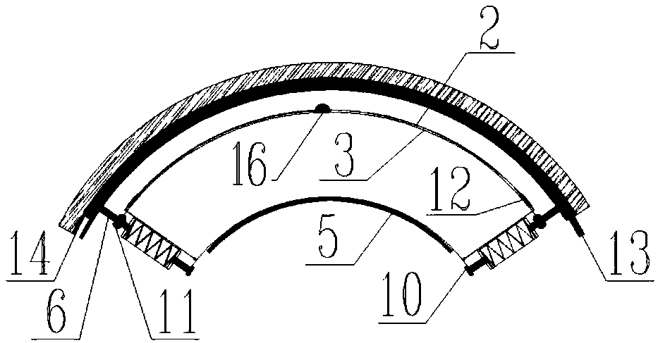
[0029] An embodiment of the present invention provides a fiber grating-based anti-collision monitoring device, including a monitoring unit, a first connecting rod group and a stainless steel ring 3, the monitoring unit includes a fiber grating sensor 12 and an optical fiber 2, and the first connecting rod The group includes at least two first connecting rods 6, and the two adjacent first connecting rods 6 are fixedly connected by a stainless steel ring 3, the optical fiber 2 is fixed on the outer surface of the stainless steel ring 3, and the optical fiber 2 It is connected with the grating fiber grating sensor 12.

[0030] From this it can be seen that if Figure 1 to Figure 3 As shown, the fiber grating sensor 12 is connected with the optical fiber 2, the optical fiber 2 is laid and fastened on the stainless steel ring 3, the two ends of the stainless steel ring 3 are connected with the first connecting rod 6, and in this embodiment the first connecting rod 6 is made of carb...

Embodiment 2

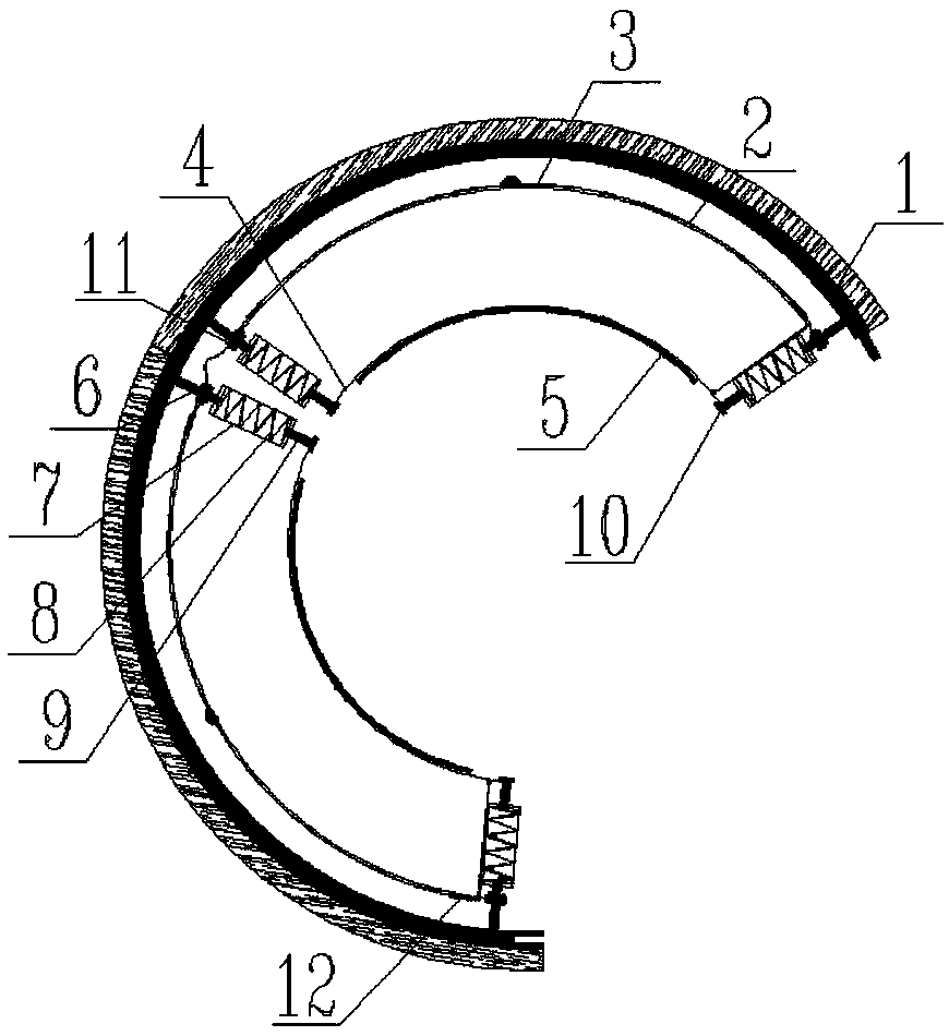
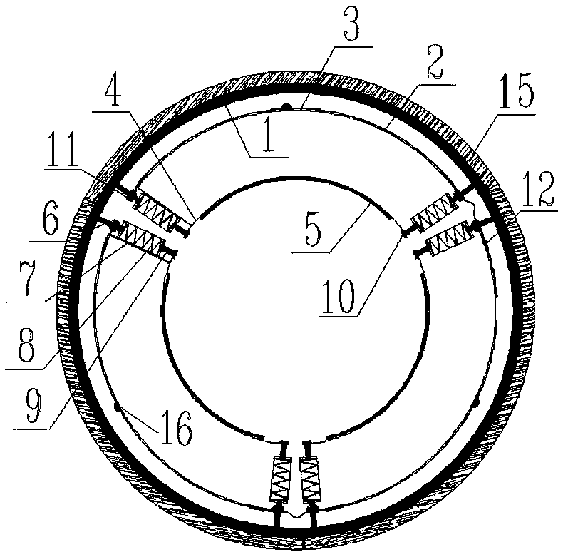
[0039] The structure of this embodiment is substantially the same as that of the embodiment, the difference is that the stainless steel ring 3 includes a plurality, each of the stainless steel rings 3 is bonded with an optical fiber 2, and the two ends of the stainless steel ring 3 are provided with protrusions 13 and recesses. The groove 14 is inserted and fitted between two adjacent stainless steel rings 3 through the protrusion 13 and the groove 14 . From this it can be seen that Figure 2 to Figure 4 As shown, the device consists of three stainless steel rings 3, and two adjacent stainless steel rings 3 are inserted and fitted through protrusions 13 and grooves 14, and holes can also be drilled at the mating places and connected with bolts.

[0040] In a preferred solution, each of the stainless steel rings 3 is covered with a rubber sleeve 15 . It can be seen that the obstacle directly collides with the rubber sleeve 15, and the rubber sleeve 15 plays the role of buffer ...

Embodiment 3

[0043] The structure of this embodiment is substantially the same as that of Embodiment 1, except that Figure 8 As shown, the stainless steel ring 3 is covered with an optical fiber 2, and then the optical fiber 2 is covered with a carbon fiber protective ring 1. The fiber grating sensor 12 can also be directly arranged on the carbon fiber protection ring 1 without the stainless steel ring 3 .

[0044] Beneficial effects of the present invention: the anti-collision monitoring device based on optical fiber grating provided by the present invention, by laying optical fiber and optical fiber grating sensor on the stainless steel ring, when an obstacle collides with the device, the stainless steel ring will be deformed, and the optical fiber grating sensor This deformation can be monitored. With strain as the monitoring variable, fiber grating is used as the collision monitoring sensor, which has sensitive monitoring, fast signal transmission, small loss along the process, and a...


PUM


Abstract

The invention belongs to the technical field of industrial robots, and specifically provides an anti-collision monitoring device based on fiber bragg grating. Through laying an optical fiber and a fiber grating sensor on a stainless steel ring, when an obstacle collides with the device, the stainless steel ring is deformed, and the fiber grating sensor can detect the deformation. With strain as amonitoring variable and a fiber bragg grating as a collision monitoring sensor, the device is sensitive in monitoring, fast in signal transmission, low in on-way loss, and resistant in electromagneticinterference. A robot can receive a braking signal at the moment of collision. Multiple collision buffering measures such as rubber sleeves and springs can effectively reduce impact force caused by the collision on the obstacle and a robot body. The device has low cost, is suitable for large-area promotion and application, and signal sensing and transmission adopt optical signals instead of electrical signals, and stability is higher, and damages to a robot host caused by leakage are prevented.

Description

technical field [0001] The invention belongs to the technical field of industrial robots, and in particular relates to an anti-collision monitoring device based on an optical fiber grating. Background technique [0002] With the development of computer and robot technology, the application of robots in all walks of life is becoming more and more common. Industrial robots represented by mechanical arms are replacing workers for full-scale automation. Generally, it is not suitable to set up obstacles that affect its work within the working radius of the robot, but sometimes due to the limitation of the working environment, when the robot must work in a small space or a space with obstacles (such as an automatic refueling robot), the corresponding collision monitoring and Protection measures are very necessary, but most of the existing robots emphasize avoiding collisions from the perspective of algorithms or early trajectory planning. This method of avoiding collisions is less...

Claims


Application Information

Patent Timeline
Patent Type & Authority Applications(China)
IPC IPC(8): G01B11/16
CPCG01B11/165
Inventor 徐剑乔张志斌杜永新蒋金辉王松林史义雄
Owner CHINA RAILWAY SIYUAN SURVEY & DESIGN GRP
Why Eureka
Try Eureka