
Energy supplying method and system for ultra-high energy efficiency cooling and heating coproduction area

A technology of energy supply and energy efficiency, applied in the energy field, can solve the problems of increasing initial investment, reducing the efficiency of refrigeration systems, reducing the life of compressors, etc., achieving the effects of solving energy waste and environmental problems, obvious energy saving effects, and reducing overheating losses

Inactive Publication Date: 2019-03-08
中建五局第三建设有限公司
View PDF14 Cites 5 Cited by
  • Summary
  • Abstract
  • Description
  • Claims
  • Application Information

AI Technical Summary

Problems solved by technology

[0004] The existing condensation heat recovery technology is to directly pass the domestic hot water that needs to be heated into the condenser instead of the cooling medium and repeat the cycle to increase the water temperature, which causes large fluctuations in the condensation pressure and seriously affects the stable operation of the refrigerator. The power consumption of the machine reduces the life of the compressor
At the same time, the temperature of domestic hot water produced is often not high enough, and other technical measures need to be taken, such as using heat pump technology (air source or water source) and electric heating technology or gas as an auxiliary heat recovery system. If the heat pump water heater will increase a lot of initial invest
Using electric heaters or fuel-fired gas boilers will not only increase the initial investment, but also use electricity, fuel oil or gas for heating, such as domestic hot water, which will lead to a reduction in the primary energy efficiency of the entire system
Simply increasing the condensation temperature will reduce the efficiency of the refrigeration system

Method used


Image

  • Energy supplying method and system for ultra-high energy efficiency cooling and heating coproduction area

Examples


Embodiment Construction

[0053] The present invention will be further described in detail below in conjunction with the accompanying drawings and specific embodiments.

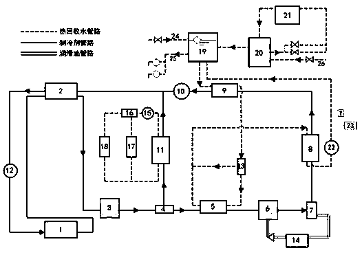
[0054] An ultra-high-efficiency cooling and heating regional energy supply system, including an evaporator, a low-pressure compressor, a high-pressure compressor, a high-temperature condenser, a low-temperature condenser, an expansion valve, an electric three-way valve, a circulating water pump, a temperature sensor, a heating The recovered gas-liquid separator, solar heat collector and solar water storage tank form a dual compressor, double condenser and solar hot water auxiliary system. Make full use of the waste heat of the regional energy supply system of combined cooling and heating, and increase the efficiency of the total energy system by 5%-10%. Recovery of refrigeration system condensation heat up to 50% -70%. Comprehensive utilization of the cooperation between high-pressure and low-pressure compressors and high-temperature...


PUM


Abstract

The invention provides an energy supplying method and system for an ultra-high energy efficiency cooling and heating coproduction area. The energy supplying method comprises the steps that (1) a refrigerant loop is arranged, specifically, a low-temperature gaseous refrigerant output by an evaporator is subjected to gas-liquid separation and heat exchanging, then compressed into medium-temperatureand medium-pressure superheated refrigerant steam, and the medium-temperature and medium-pressure superheated refrigerant steam enters a low-temperature side shunt and a high-temperature side shunt; (2) the high-temperature side shunt is arranged, specifically, the superheat degree of the medium-temperature and medium-pressure superheated refrigerant steam is decreased, then the medium-temperatureand medium-pressure superheated refrigerant steam is compressed into high-temperature and high-pressure refrigerant steam, the high-temperature and high-pressure refrigerant steam is condensed through a high-temperature condenser and cooled again through a subcooler, the pressure of the high-temperature and high-pressure refrigerant steam is decreased to the pressure of the low-temperature side through an expansion valve, and then the high-temperature and high-pressure refrigerant steam is converged with a refrigerant of the low-temperature side shunt; and (3) the low-temperature side shunt is arranged, specifically, after entering a low-temperature condenser to be condensed, the medium-temperature and medium-pressure superheated refrigerant steam is converged with the refrigerant of thehigh-temperature side shunt to form a refrigerant gas-liquid mixture, and then the refrigerant gas-liquid mixture is subjected to heat exchange with low-temperature steam output by the evaporator. Theinvention further comprises the energy supplying system for the ultra-high energy efficiency cooling and heating coproduction area. The energy supplying method and system have the advantages that theefficiency is high, operation is stable, the cost is saved, and the energy-saving effect is significant.

Description

technical field [0001] The invention relates to the field of energy technology, in particular to an ultra-high energy-efficiency combined cooling and heating regional energy supply method and system. Background technique [0002] Conventional air conditioning systems are mainly composed of refrigerant circulation, cooling water (or air) circulation, and chilled water (or air) circulation. The cooling load of the air-conditioned room enters the refrigerant cycle through the evaporator, becomes part of the condensed heat exhaust, and then is discharged into the atmosphere through the cooling water (or air) cycle. Therefore, for conventional air-conditioning refrigerators, the condensation heat of the air-conditioning system is directly discharged into the atmosphere without being utilized. Refrigeration units emit a large amount of condensation heat to the atmosphere when operating under air-conditioning conditions, and usually the condensation heat can reach 1.15 to 1.3 time...

Claims


Application Information

Patent Timeline
IPC IPC(8): F25B1/10F25B41/04F25B49/02F24D17/00F24D17/02F25B41/31
CPCF24D17/0021F24D17/02F25B1/10F25B49/02F25B41/20
Inventor 郭朋鑫粟元甲李洪强林冰宁志强吴掌平
Owner 中建五局第三建设有限公司
Learn More