Heat pump type tube bundle drier

A tube bundle drying and heat pump technology, which is used in heat pumps, dryers, drying solid materials, etc., to relieve energy shortages, improve drying thermal efficiency, and reduce the probability of running failures.

Pending Publication Date: 2019-03-08
ZHENGZHOU WANGU MACHINERY
View PDF8 Cites 0 Cited by
  • Summary
  • Abstract
  • Description
  • Claims
  • Application Information

AI Technical Summary

Problems solved by technology

[0008] In view of the above prior art, the problem to be solved in the present invention is to provide a heat pump tube bundle dryer by organically combining the air source heat pump technology with the traditional tube bundle dryer, which can not only improve the drying heat efficiency of the tube bundle dryer, but also effectively Energy saving, also because of the use of electric energy, a clean energy source, to reduce environmental pollution, achieve energy saving and environmental protection, high drying efficiency, and good quality of dried products

Method used


Image

  • Heat pump type tube bundle drier
  • Heat pump type tube bundle drier

Examples


Embodiment 1

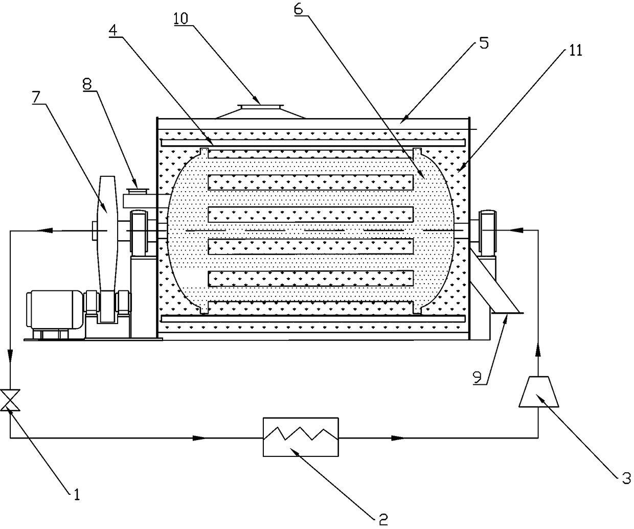
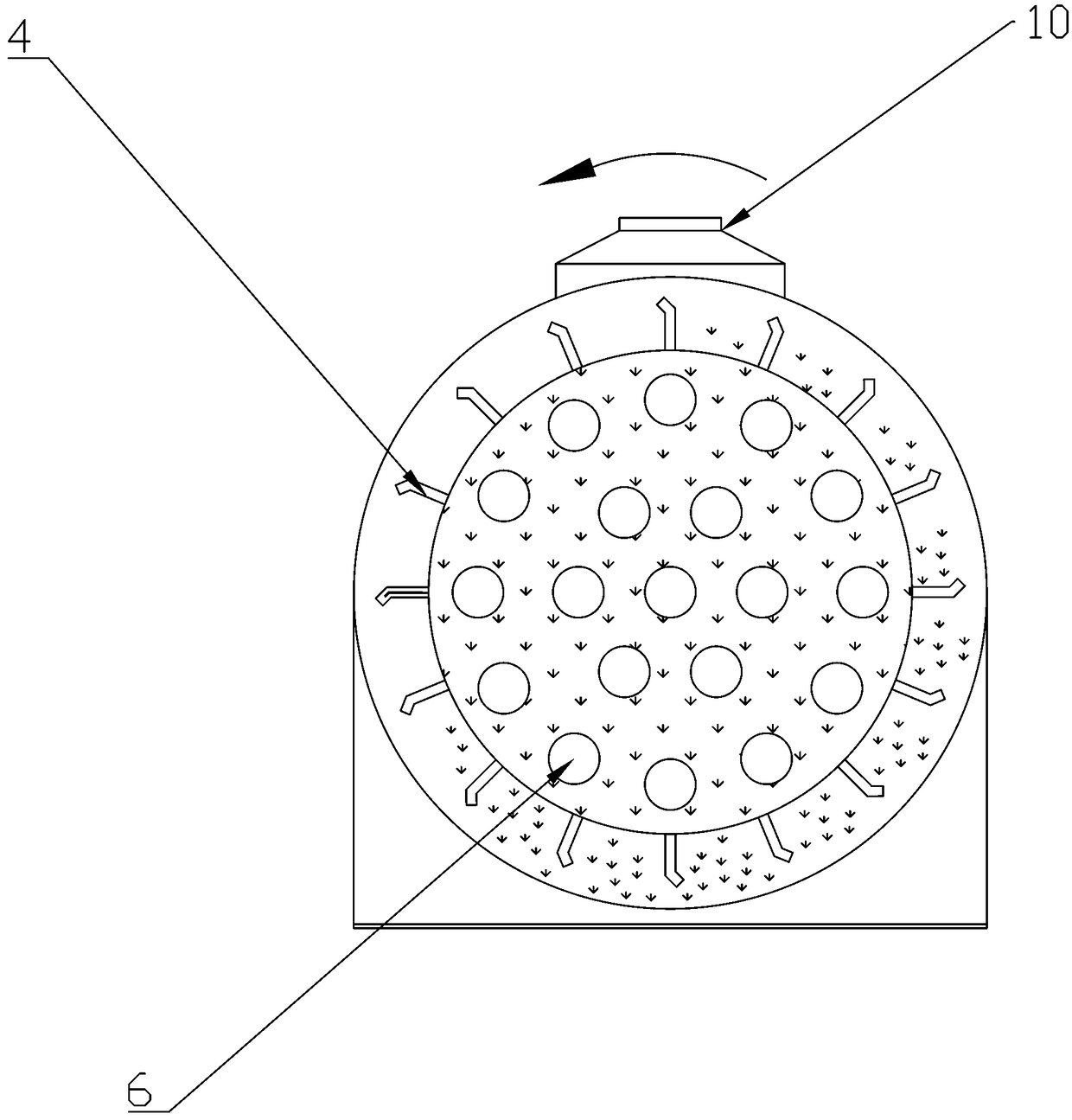
[0025] Such as figure 1 figure 2 As shown, a heat pump tube bundle dryer includes a heat pump unit and a tube bundle dryer unit. The heat pump unit is a closed circuit, and the heat pump unit includes an expansion valve 1, an evaporator 2, a compressor 3 and a dryer unit connected in sequence. The shared tube bundle condenser 6, the heat pump working fluid inlet of the expansion valve 1 is connected to the heat pump working fluid outlet of the tube bundle condenser 6, the heat pump working fluid outlet of the compressor 3 is connected to the heat pump working fluid inlet of the tube bundle condenser 6; the tube bundle dryer The unit includes a tube shell 5, a lifting plate 4, a transmission mechanism 7, a material inlet 8, a material outlet 9, an exhaust gas outlet 10, and a tube bundle condenser shared with the heat pump unit. The tube bundle condenser 6 and the lifting plate 4 are installed in the tube shell Inside 5, the tube bundle condenser 6, as a common part of the he...

Embodiment 2

[0029] Embodiment 1 is basically the same as Embodiment 2, except that the tube bundle condenser 6 is arranged in a circular arrangement with a single tube pass, and multiple central exhaust pipes are arranged, and the exhaust gas outlet 10 can be connected to an exhaust gas suction fan. Through multiple central pipes, the heating area of ​​the material can be increased, and the drying efficiency of the material can be improved. Through the waste gas suction fan, the water vapor generated by material drying can be sucked away in time, and the drying efficiency of the dryer can be improved.

Embodiment 3

[0031] The rotating mechanism 7 is connected with the central rotating shaft of the tube bundle condenser 6 and the lifting plate 4, and the rotating mechanism 7 is provided with a speed change transmission. The speed of the rotating mechanism is adjusted by the speed-adjusting transmission, so as to control the speed of the lifting board, to control the flow speed of the material, and to realize the sufficient drying of the material.

[0032] As a person skilled in the art, it needs to be explained that the moving direction of the material can also be in phase with the direction in which the heat pump working fluid enters.


PUM


Abstract

The invention provides a heat pump type tube bundle drier. The heat pump type tube bundle drier comprises a heat pump unit and a tube bundle drier unit, wherein the heat pump unit is a closed loop, the heat pump unit comprises an expansion valve, an evaporator, a compressor and a tube bundle condenser which are connected in sequence, and the tube bundle condenser is shared to be used in the drierunit; the tube bundle drier unit comprises a tube shell, a shoveling plate, a transmission mechanism, a feeding port, a discharging port, an exhaust gas outlet and the tube bundle condenser which is shared to be used in the heat pump unit; the tube bundle condenser and the shoveling plate are installed inside the tube shell, and the tube bundle condenser, as a part shared by the heat pump unit andthe drier unit, acts as not only the condenser of the heat pump unit, but also the heater of the pipe bundle drier unit. Through the organic combination of an air source heat pump technology and a traditional tube bundle drier, the heat pump type tube bundle drier is provided, the drying thermal efficiency of the tube bundle drier is improved, therefore the goal of energy conservation and environment protection, high drying efficiency and good quality of dried products is achieved.

Description

technical field [0001] The invention belongs to the field of grain drying equipment, in particular to a heat pump tube bundle dryer. Background technique [0002] Heat pump tube bundle dryer is used for drying non-viscous or semi-viscous materials such as granules, flakes and powders in grain, food, feed, light industry, starch and other industries. [0003] Material drying is the process of adding heat to the wet material and removing the moisture in the wet material. Since the sensible heat and latent heat of evaporation required for the temperature rise of the wet material and the evaporation of the water in the wet material need to be provided during drying, the material drying process requires a lot of Therefore, in the drying process, on the premise of ensuring the drying quality of materials, improving drying efficiency and reducing energy consumption in the drying process are important tasks for energy saving and emission reduction in the drying industry. [0004] H...

Claims


Application Information

Patent Timeline
Patent Type & Authority Applications(China)
IPC IPC(8): F26B17/20F26B23/10F26B23/00F26B25/00F25B30/06
CPCF25B30/06F26B17/20F26B23/005F26B23/10F26B25/005
Inventor 陆应郭桂霞陈正权李衡秦强李志刚石明侯守娟杨凯敏曹伟
Owner ZHENGZHOU WANGU MACHINERY
Why Eureka
Try Eureka