Thermal barrier coating for gas turbine blades and preparation method of coating

A technology of thermal barrier coatings and turbine blades, applied in coatings, metal material coating processes, fusion spraying, etc., to achieve compact structure, improve overall performance, and reduce production costs

Inactive Publication Date: 2019-03-12
SHENYANG LIMING AERO-ENGINE GROUP CORPORATION
View PDF4 Cites 3 Cited by
  • Summary
  • Abstract
  • Description
  • Claims
  • Application Information

AI Technical Summary

Problems solved by technology

[0007] The purpose of the present invention is to provide a high-reliability thermal barrier coating f

Method used


Image

  • Thermal barrier coating for gas turbine blades and preparation method of coating

Examples


Example Embodiment

[0021] Example 1

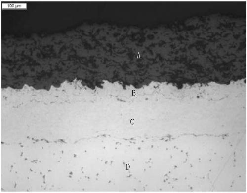
[0022] The thermal barrier coating is prepared using the superalloy base material of the gas turbine first-stage turbine blade as the carrier. The process flow is: incoming inspection → acetone degreasing → visual inspection → dry sand blowing → cleaning → fixture protection → clamping → preheating → super Sonic spraying MCrAlY dense layer → supersonic spraying MCrAlY rough layer → heat treatment → plasma spraying YSZ surface layer → inspection.

[0023] Dry sand blowing treatment before spraying is to clean and activate the alloy surface of the parts, thereby improving the bonding strength between the MCrAlY bottom layer and the alloy matrix.

[0024] The coating preparation steps are:

[0025] 1) Supersonic spraying MCrAlY (M=Ni) dense layer with a thickness of 0.13mm, and the particle size of MCrAlY powder used for spraying is -88+16μm;

[0026] 2) Supersonic spraying MCrAlY (M=Ni) rough layer with a thickness of 0.07mm, the particle size of MCrAlY powder used for...

Example Embodiment

[0030] Example 2

[0031] The difference from Example 1 is:

[0032] The thickness of the dense layer of supersonic spraying MCrAlY (M=Ni+Co) is 0.09mm; the thickness of the rough layer of supersonic spraying MCrAlY (M=Ni+Co) is 0.05mm; the surface roughness Ra of the rough layer after spraying is 12μm; plasma spraying The thickness of the YSZ surface layer is 0.35mm. The thermal barrier coating has the advantages of good oxidation and corrosion resistance and high interface bonding strength.

Example Embodiment

[0033] Example 3

[0034] The difference from Example 1 is:

[0035] The thickness of the dense layer of supersonic spraying MCrAlY (M=Co) is 0.15mm; the thickness of the rough layer of supersonic spraying MCrAlY (M=Co) is 0.06mm; the surface roughness Ra of the rough layer after spraying is greater than 10μm; the thickness of the plasma spraying YSZ surface layer It is 0.45mm. The thermal barrier coating has the advantages of good oxidation and corrosion resistance and high interface bonding strength.


PUM

PropertyMeasurementUnit
Thicknessaaaaaaaaaa
Roughnessaaaaaaaaaa

Abstract

The invention provides a thermal barrier coating with a MCrAlY bottom layer compact in structure and large in roughness according to requirements of gas turbine blades for low-cost and long-service-life thermal barrier coatings. The specific implementation process includes the steps that 1, a supersonic spraying method is adopted to prepare a MCrAlY compact layer with the thickness of 0.07-0.15 mmon the surface of a part; 2, the supersonic spraying method is adopted to prepare a MCrAlY rough layer with the thickness of 0.05-0.07 mm on the surface of the part; 3, the part where the coatings are sprayed is subjected to vacuum heat treatment, wherein the heat treatment temperature is 1050+/-10 DEG C, heat preservation is carried out for 3+/-0.5 h, and the blades are cooled to 200 DEG C or below along with a furnace, cooled to 80 DEG C or below by introducing argon and then taken out of the furnace; and 4, an atmospheric plasma spraying method is adopted to prepare a YSZ ceramic surface layer with the thickness of 0.20-0.50 mm on the surface of the part. The thermal barrier coating has the advantages of being good in oxidation corrosion resistance, high in interface bonding strength and the like, and the requirements of the gas turbine blades for the low-cost and long-service-life thermal barrier coatings are met.

Description

technical field [0001] The invention belongs to the technical field of protective coatings for gas turbine blades, and particularly provides a low-cost, long-life, high-reliability thermal barrier coating for gas turbine blades and a preparation method thereof. Background technique [0002] Gas turbine turbine blades have a harsh service environment and have been subjected to the impact and erosion of high-temperature gas for a long time. The surface needs to be coated with a MCrAlY metal bonded primer with good oxidation and corrosion resistance, where M is Ni, Co or Ni+Co, and has a low thermal conductivity. the Y 2 o 3 Partially stabilized ZrO 2 , that is, thermal barrier coating TBCs composed of YSZ ceramic surface layer to improve its anti-ablation ability and prolong its service life and reliability. [0003] As a transition layer between the ceramic surface layer and the superalloy substrate, the MCrAlY bonding layer has two main functions: one is to reduce the the...

Claims


Application Information

Patent Timeline
IPC IPC(8): C23C4/073C23C4/129C23C4/11C23C4/134C23C4/18
CPCC23C4/073C23C4/11C23C4/129C23C4/134C23C4/18
Inventor 程玉贤芦国强张艺馨王璐李晓罡
Owner SHENYANG LIMING AERO-ENGINE GROUP CORPORATION
Why Eureka
Try Eureka