
Detection method of tunnel lining crack based on mobile type three-dimensional laser scanning technique

A three-dimensional laser and scanning technology, applied in the field of tunnel lining crack detection, can solve the problems of low efficiency, inefficient point cloud and high cost, save material cost, solve over-dependence and improve efficiency.

Active Publication Date: 2019-03-12
SOUTHEAST UNIV
View PDF16 Cites 13 Cited by
  • Summary
  • Abstract
  • Description
  • Claims
  • Application Information

AI Technical Summary

Problems solved by technology

[0005] The technical problem to be solved by the present invention is to provide a tunnel lining crack detection method based on mobile three-dimensional laser scanning technology for the problems of complex operation, low efficiency, harsh environmental requirements, and high cost of the existing domestic tunnel lining crack detection technology, which can be used in Uninterrupted, fast and accurate acquisition of the target point cloud during the movement, and can use this as a medium to detect tunnel lining crack information
On the one hand, it solves the complex and low-efficiency problems of static station 3D laser scanning technology and the problem of sparse point clouds between two adjacent stations; on the other hand, it solves the harsh requirements of photogrammetry and other technical means for light

Method used


Image

  • Detection method of tunnel lining crack based on mobile type three-dimensional laser scanning technique
  • Detection method of tunnel lining crack based on mobile type three-dimensional laser scanning technique
  • Detection method of tunnel lining crack based on mobile type three-dimensional laser scanning technique

Examples


Embodiment Construction

[0027] Embodiments of the present invention will be described below in conjunction with the accompanying drawings.

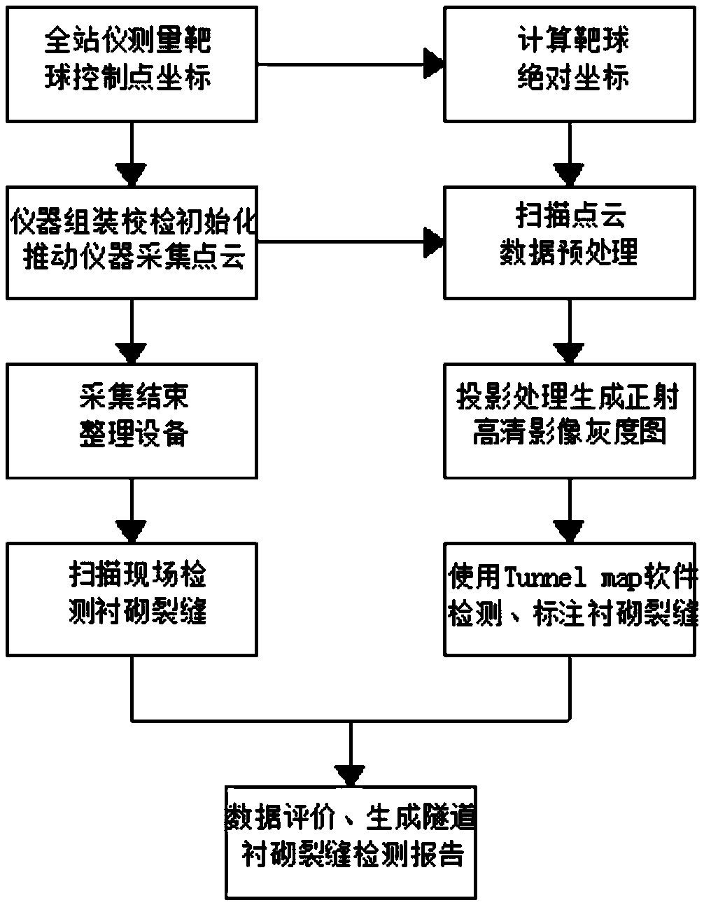
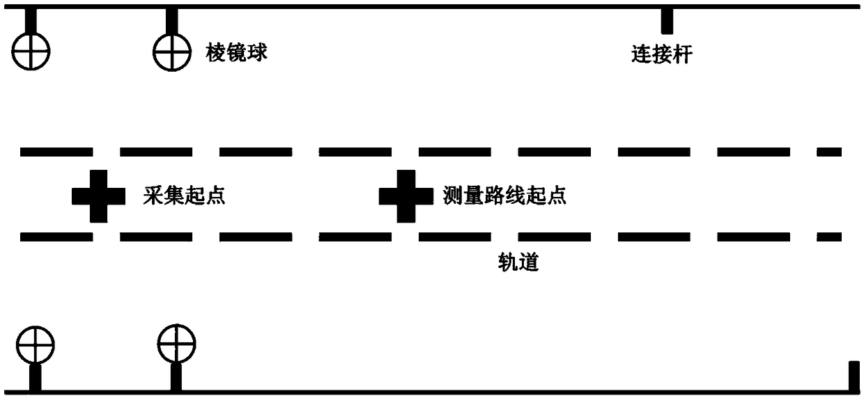
[0028] Such as figure 1 As shown, the present invention designs a tunnel lining crack detection method based on mobile 3D laser scanning technology. This method is based on conventional 3D laser scanning technology, combined with mobile rail trolley and IMU technology, and combined with point cloud processing The technical means to obtain the crack information on the surface of the tunnel lining mainly include field data acquisition methods and point cloud data processing methods. Field data collection methods mainly refer to pre-collection preparations, data collection, and collection end work; point cloud data processing methods mainly refer to point cloud data denoising, point cloud data splicing and control, tunnel scanning point cloud panorama processing, analysis and acquisition of lining cracks . The pre-acquisition preparatory work includes instrument ...


PUM


Abstract

The invention discloses a detection method of a tunnel lining crack based on a mobile type three-dimensional laser scanning technique. The detection method comprises the following steps of determiningthe length and the route change trend of the measuring route, and arranging a plurality of control points on a tunnel wall along the measuring route; when a scanning vehicle is moved, performing static self-calibrating collection on the cross section of a tunnel by a three-dimensional laser scanner, so as to obtain the data of the point cloud of the cross section of the tunnel; pre-treating the data of the point cloud of the cross section of the tunnel; when the scanning vehicle is moved, obtaining the coordinates of each control point through a total station, and controlling under the same coordinate system; projecting the pretreated data of the point cloud of the cross section of the tunnel onto the standard cross section of the tunnel to form an orthographic gray scale plan; accordingto the orthographic gray scale plan and the coordinates of each control point, measuring the data of crack at the tunnel lining surface, marking, calculating, and outputting. The detection method hasthe advantages that a large amount of point clouds at the tunnel lining surface can be obtained, and be treated and analyzed, so as to obtain the information of the crack at the tunnel lining surface;the tunnel lining crack can be more quickly and accurately detected.

Description

technical field [0001] The invention relates to a tunnel lining crack detection method based on mobile three-dimensional laser scanning technology, which belongs to the technical field of tunnel surveying and mapping. Background technique [0002] With the rapid development of the country's economy and the continuous advancement of urbanization, the number of railway tunnels continues to increase, which greatly improves the convenience of people's travel. However, due to the continuous changes in the external environment and geological conditions, as well as the design, construction, management and surrounding buildings Influenced by construction and other aspects, during the use of the tunnel, cracks, leakage, and block failures often occur, which seriously threaten the normal and safe use of the tunnel. An efficient and accurate detection technology is urgently needed to detect the state of the tunnel lining . In the phenomena of cracks, leakage, and block loss, cracks ar...

Claims


Application Information

Patent Timeline
Patent Type & Authority Applications(China)
IPC IPC(8): G01N21/88
CPCG01N21/88
Inventor 吴向阳夏金周吴中奇
Owner SOUTHEAST UNIV
Learn More