Low energy consumption distillation equipment for ultrapure ammonia

A technology of energy consumption and rectification, which is applied in the field of ultra-pure ammonia low-energy rectification equipment, which can solve the problems of small contact area, high water content, and poor rectification effect, so as to improve distillation effect, utilization rate and utilization rate high effect

Active Publication Date: 2019-03-15
浙江英德赛半导体材料股份有限公司
View PDF7 Cites 2 Cited by
  • Summary
  • Abstract
  • Description
  • Claims
  • Application Information

AI Technical Summary

Problems solved by technology

[0004] The object of the present invention is to provide a rectification equipment with low energy consumption for ultra-pure ammonia, to solve the problem that the contact area between the liquid phase and the countercurrent gas phase under the action of the gravity field is small, and the efficiency of mass transfer is low, which makes the rectification process difficult. The effect of distillation is poor, and the water content is high; there is no flow detection and temperature detection device, it is inconvenient to know the situation and degree of distillation; there is no recovery and treatment device for surplus, which makes the utilization rate of ammonia gas low, and the temperature control device And the effect of the condensing device is slow, and the fixed temperature cannot be reached in time and accurately, so that the problem of accurate separation and purification of ammonia gas

Method used


Image

  • Low energy consumption distillation equipment for ultrapure ammonia
  • Low energy consumption distillation equipment for ultrapure ammonia
  • Low energy consumption distillation equipment for ultrapure ammonia

Examples


Embodiment Construction

[0027] The following will clearly and completely describe the technical solutions in the embodiments of the present invention with reference to the accompanying drawings in the embodiments of the present invention. Obviously, the described embodiments are only some, not all, embodiments of the present invention. Based on the embodiments of the present invention, all other embodiments obtained by persons of ordinary skill in the art without making creative efforts belong to the protection scope of the present invention.

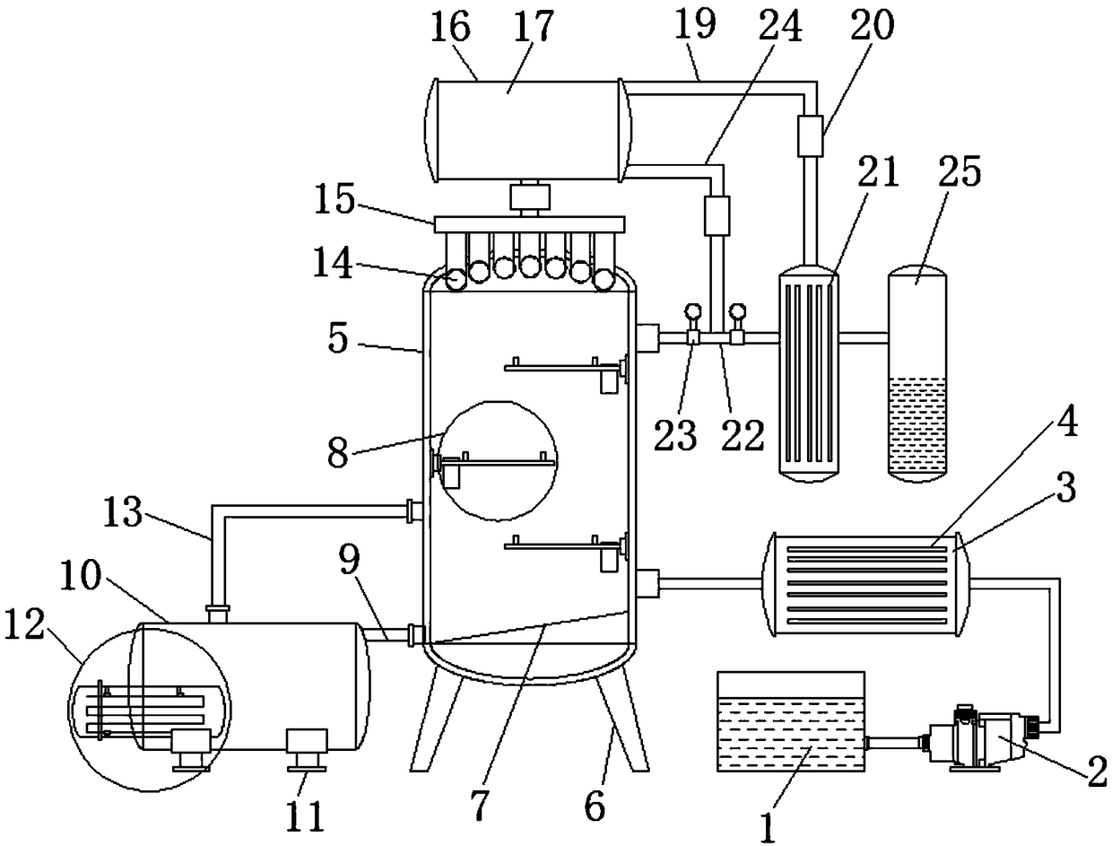
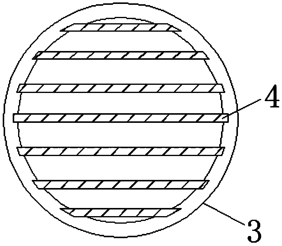
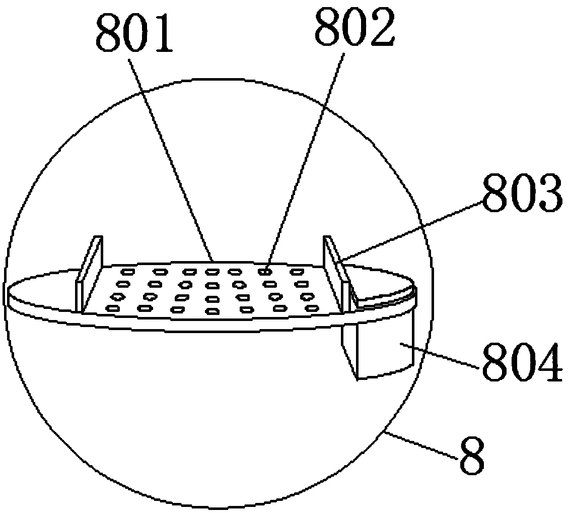
[0028] see Figure 1-6 , the present invention provides a technical solution: an ultra-pure ammonia low-energy rectification equipment, including a raw material tank 1, a centrifugal pump 2, a preheater 3, an electric heating plate 4, a tower body 5, a first leg 6, a lower Material plate 7, tray structure 8, first connecting pipe 9, tower kettle 10, second leg 11, reboiler 12, second connecting pipe 13, gas outlet pipe 14, gas collecting chamber 15, total cond...


PUM


Abstract

The invention discloses low energy consumption distillation equipment for ultrapure ammonia. The low energy consumption distillation equipment comprises a raw material tank and a total condenser, wherein a centrifugal pump is connected to the right end of the raw material tank; electric heating panels are equidistantly arranged inside a preheater in a clamping connection manner; a tower body is connected to the left end of the preheater; a discharging plate is arranged at the lower end inside the tower body; a first connecting pipe is connected to the lower end of the left end surface of the tower body; a reboiler is arranged on the left side inside a reactor in a penetrating manner; a second connecting pipe is connected to the upper surface of the reactor in a penetrating manner; gas outlet pipes are equidistantly connected to the upper end of the tower body in a penetrating manner; the total condenser is connected to the upper end of a gas collecting cavity; a cold water pipe is arranged inside a refrigerating cavity. The low energy consumption distillation equipment for the ultrapure ammonia has the relatively high mass transfer efficiency so as to obtain a relatively good distillation effect; a flow and temperature detecting device facilitates the learning of distillation conditions and degree; by use of an excess recovery treatment device, a temperature control device anda condensation device, the effect is relatively fast and ammonia gas is accurately separated and purified.

Description

technical field [0001] The invention relates to the technical field related to rectification equipment, in particular to an ultra-pure ammonia low-energy rectification equipment. Background technique [0002] With the rapid development of my country's solar photovoltaic industry and semiconductor light-emitting devices, the demand for ultra-pure ammonia will increase significantly, but the domestic production level of ultra-pure ammonia is still relatively backward, requiring a lot of calculations and experimental research , the developed energy-saving refining process technology, so that not only can obtain qualified high-purity ammonia gas, but also have a great energy-saving effect, such as the development of science and technology and the increasing social demand for electronic products, new energy-saving lighting devices, and clean energy. The demand for high-purity ammonia is also increasing. [0003] For example, in the production of high-brightness LED devices, due to...

Claims


Application Information

Patent Timeline
IPC IPC(8): C01C1/02B01D3/14B01D3/32
CPCB01D3/14B01D3/32B01D3/322C01C1/02C01C1/024
Inventor 赵晓兰丁高松潘佳伟鄢芝勇
Owner 浙江英德赛半导体材料股份有限公司
Why Eureka
Try Eureka