
Oil-gas separator assembly of crankcase ventilation system and vehicle

An oil-gas separator and crankcase ventilation technology, which is applied in the field of vehicles, can solve problems such as engine oil loss, increased air pollution, and oil leakage from seals, and achieve the effects of increasing the flow cross-sectional area, increasing the flow rate, and improving the separation efficiency

Active Publication Date: 2019-03-15
台州滨海吉利发动机有限公司 +1
View PDF8 Cites 2 Cited by
  • Summary
  • Abstract
  • Description
  • Claims
  • Application Information

AI Technical Summary

Problems solved by technology

If the exhaust gas flowing into the crankcase is not discharged, high pressure will be formed in the crankcase, causing the seal to leak oil, and the oil will seep from the crankshaft oil seal, crankcase gasket, etc.
At the same time, the oil vapor lost to the atmosphere will increase the pollution of the atmosphere

Method used


Image

  • Oil-gas separator assembly of crankcase ventilation system and vehicle
  • Oil-gas separator assembly of crankcase ventilation system and vehicle
  • Oil-gas separator assembly of crankcase ventilation system and vehicle

Examples


Embodiment Construction

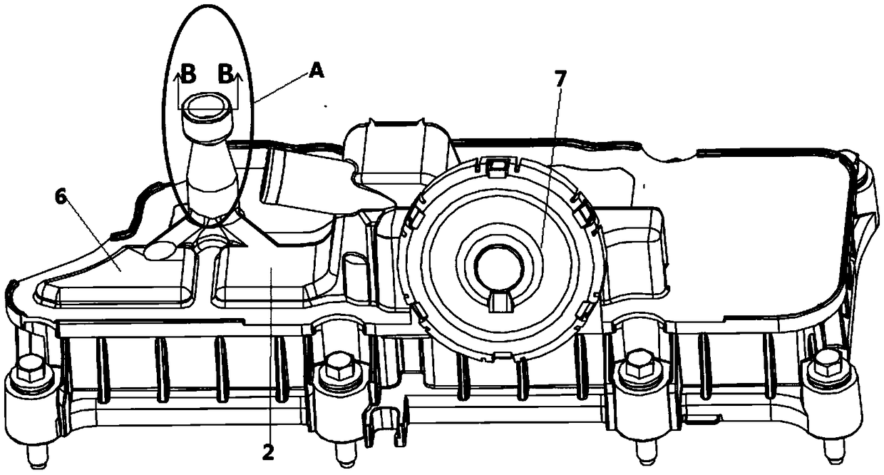
[0031] figure 2 is a three-dimensional schematic diagram of an oil-gas separator according to an embodiment of the present invention, image 3 yes figure 2 A schematic cross-sectional view along the B-B line in A area. see image 3 , see also figure 2 , this embodiment takes image 3 To explain to the Lord. The crankcase ventilation system oil-air separator assembly includes a booster chamber 1 and a separation chamber 2 . The gas inlet of the boost chamber 1 communicates with the supercharger for accommodating fresh air pressurized by the supercharger when the supercharger is in a transitional state. The separation chamber 2 communicates with the gas outlet 3 of the pressurization chamber 1 and is used to accommodate the waste gas separated by the oil-gas separator. Wherein, the flow area of ​​the gas outlet 3 of the pressurized chamber 1 is smaller than the flow area of ​​the gas inlet, so that the speed of the pressurized fresh air flowing out from the gas outlet...


PUM


Abstract

The invention discloses an oil-gas separator assembly of a crankcase ventilation system and a vehicle, relating to the technical field of vehicles. The oil-gas separator assembly of the crankcase ventilation system comprises a pressurization chamber, and a gas inlet thereof communicates with the pressurization chamber for accommodating pressurized fresh air. The oil-gas separator assembly also includes a separation chamber in communication with the gas outlet of the pressurization chamber for containing the exhaust gas separated by an oil-gas separator, wherein an overflow area of the gas outlet of the pressurization chamber is smaller than an overflow area of the gas inlet thereof, so that the flowing-out speed of the pressurized fresh air out of the gas outlet is faster than the flowing-in speed of the pressurized fresh air from the gas inlet, thereby driving the exhaust gas in the separation chamber out of the separation chamber together and enabling the exhaust gas to flow toward the engine of the vehicle to participate in combustion. The invention also provides a vehicle, comprising the oil-gas separator assembly. The invention can improve the separation efficiency of the oil-gas separator when the supercharger is just intervened in the working condition or exits from the working condition.

Description

technical field [0001] The invention relates to the technical field of vehicles, in particular to an oil-gas separator assembly of a crankcase ventilation system and a vehicle. Background technique [0002] The oil-air separator is the most important part in the crankcase ventilation system. During the engine working process, the exhaust gas, unburned mixture gas and water vapor in the combustion chamber will often seep into the crankcase through the gap between the piston and the cylinder wall. Condensation of the fuel vapor escaping into the crankcase will thin the engine oil and deteriorate its performance. If the exhaust gas flowing into the crankcase is not discharged, high pressure will be formed in the crankcase, causing the seal to leak oil, and the oil will seep from the crankshaft oil seal, crankcase gasket, etc. and be lost. At the same time, the oil vapor lost to the atmosphere will increase the pollution to the atmosphere. [0003] The function of the oil-gas ...

Claims


Application Information

Patent Timeline
Patent Type & Authority Applications(China)
IPC IPC(8): F01M13/04
CPCF01M13/04F01M2013/045
Inventor 王建航贺锋陈旗奇李强刘国庆汪名月赵福成王瑞平
Owner 台州滨海吉利发动机有限公司
Features
  • Generate Ideas
  • Intellectual Property
  • Life Sciences
  • Materials
  • Tech Scout
  • Unparalleled Data Quality
  • Higher Quality Content
  • 60% Fewer Hallucinations
Learn More