A kind of film of depolarization beam combiner and design method thereof

A design method and depolarization technology, which is applied in the field of lasers, can solve the problem of inability to obtain high reflectivity, transmittance depolarization effect, large polarization separation of P-polarized light and S-polarized light, and inability to take both anti-reflection and high reflection into consideration. and other problems, to achieve good depolarization effect and spectral characteristics, eliminate polarization separation, and excellent spectral characteristics

Active Publication Date: 2021-07-02
润坤(上海)光学科技有限公司 +1
View PDF6 Cites 0 Cited by
  • Summary
  • Abstract
  • Description
  • Claims
  • Application Information

AI Technical Summary

Problems solved by technology

However, this initial film system cannot take into account the high-efficiency anti-reflection and high reflection of P-polarized light and S-polarized light required for laser beam combining, and the polarization separation of P-polarized light and S-polarized light is extremely large
The optimization process is extremely cumbersome, and the final film system is also extremely irregular.
At the same time, the relatively complex film structure also brings many difficulties to the precise preparation of thin films:
[0004] 1. The sensitivity of the film layer is high, and a small deposition thickness error will bring a large spectral deviation;
[0005] 2. The distribution of the film layer is messy, which may introduce greater random errors;
[0006] 3. The introduction of extremely thick and thin layers may introduce larger system errors
Many factors cause the actual spectrum to deviate far from the design spectrum, and it is impossible to obtain high reflectivity, transmittance and good depolarization effect
Another method is to use three or more materials to design. Although the depolarization effect is good, but due to the use of many materials, for most coating equipment, the actual preparation is difficult and cannot be widely promoted.
[0007] At present, there is no design that can effectively solve polarization separation and has high fabrication feasibility

Method used


Image

  • A kind of film of depolarization beam combiner and design method thereof
  • A kind of film of depolarization beam combiner and design method thereof
  • A kind of film of depolarization beam combiner and design method thereof

Examples


Embodiment

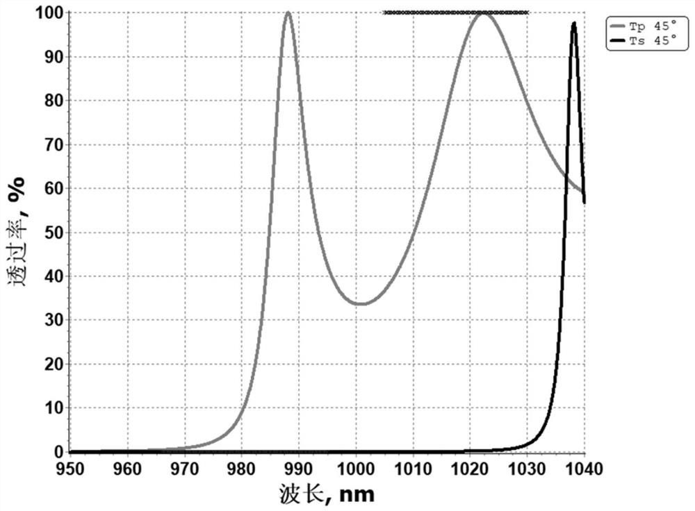
[0065] This embodiment provides a 45-degree near-infrared depolarization beam combiner film and a design method. Its combined laser beam wavelength: λ A 976nm, λ B It is 1010nm, that is, it needs to meet the high reflection of P-polarized light and S-polarized light at 976nm, and the high transmission of P-polarized light and S-polarized light at 1010nm, and eliminate the polarization separation of P-polarized light and S-polarized light. image 3 Shown is the regular high-reflection film: Sub|(HL)^20|Air transmittance spectrum, it can be seen that the initial film system has a large degree of polarization separation, even through optimization, it is difficult to completely eliminate polarization. Therefore, more effective depolarization design methods are needed.

[0066] The specific design method includes the following steps:

[0067] 45-degree near-infrared depolarization beam combiner film structure, such as figure 1 As shown, it includes a substrate 1 and a first thi...


PUM

PropertyMeasurementUnit
reflectanceaaaaaaaaaa

Abstract

The invention relates to a depolarization beam combiner film, comprising a base and a first film arranged on the base, the film structure of the first film is Sub|x 1 x 2 x 3 x 4 L...x k‑ 3 x k‑2 x k‑1 x k L|Air, where Sub is the thin-film element substrate, Air is the exit medium air, H and L are the high-refractive-index material film layer and the low-refractive-index material film layer with an optical thickness of 1 / 4 center wavelength, respectively, x 1 ~x k is the optical thickness coefficient of each film layer, and k is the total number of film layers. Compared with the prior art, the present invention has the advantages of simple optimization process, regular film system, convenient and accurate preparation, reduced preparation complexity, good depolarization effect, excellent spectral characteristics, and easy popularization and use. It has broad practical prospects and can be used for incoherent beam combining of different wavelength lasers.

Description

technical field [0001] The invention belongs to the field of lasers, and relates to an optical film, in particular to a depolarization beam combiner film and a design method thereof Background technique [0002] High-power lasers play a very important role in laser fusion, national defense, industrial production, medical equipment, space communication and aerospace technology. Some application fields have high requirements on the power of lasers, such as laser cutting and welding, automotive processing requires kilowatt-level high-power lasers, and national defense and military fields require high-power laser directional weapons. All these requirements and applications pose a new challenge to the improvement of performance indicators such as power, beam quality and output efficiency of current lasers. An effective way to increase laser output power is to use laser beam combining technology to incoherently combine laser beams of different bands to obtain multi-band, high-pow...

Claims


Application Information

Patent Timeline
Patent Type & Authority Patents(China)
IPC IPC(8): G02B5/00G02B1/10G02B27/00
CPCG02B1/10G02B5/00G02B27/0012
Inventor 吴建锋焦宏飞钮信尚汲小川张学敏张锦龙程鑫彬王占山
Owner 润坤(上海)光学科技有限公司
Why Eureka
Try Eureka