Eureka AIR delivers breakthrough ideas for toughest innovation challenges, trusted by R&D personnel around the world.

A layout structure and method suitable for passive millimeter wave human body security detector

A technology for layout structure and human body security inspection, which is applied in geological exploration using millimeter waves, optical-based geological exploration, instruments, etc. It can solve the problem of reducing the effective receiving area of ​​sparse arrays, increasing image noise and affecting image quality, and the total received energy of sparse arrays. To ensure the imaging field of view and spatial resolution, reduce edge effects, and improve the filling rate

Active Publication Date: 2020-12-04
BEIHANG UNIV
View PDF9 Cites 0 Cited by
  • Summary
  • Abstract
  • Description
  • Claims
  • Application Information

AI Technical Summary

Problems solved by technology

However, in the sparse array layout, since the element antennas are not uniformly spaced and staggered, the use of uniform-sized element antennas will reduce the effective receiving area of ​​the sparse array and reduce the total received energy of the sparse array.
In turn, it affects the sidelobe of the pattern of the sparse array beamforming, increases the beam efficiency, reduces the temperature sensitivity of the image, and increases the image noise to affect the image quality.

Method used

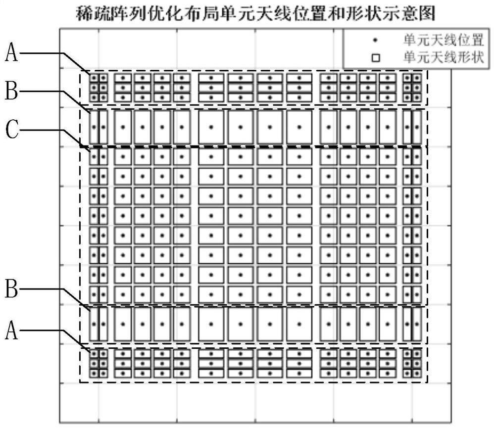
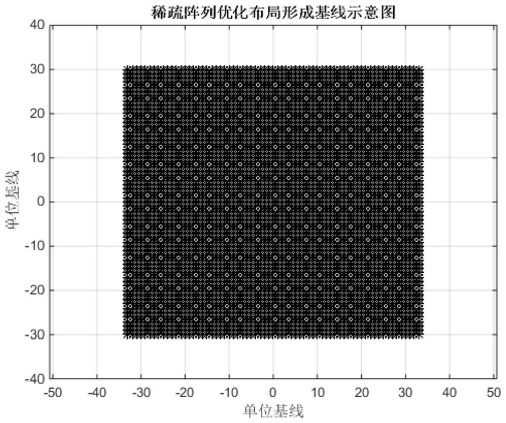
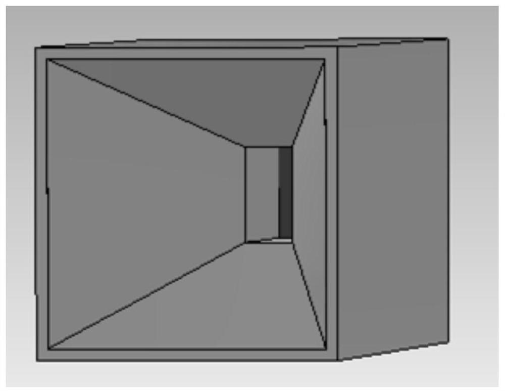

Image

  • A layout structure and method suitable for passive millimeter wave human body security detector
  • A layout structure and method suitable for passive millimeter wave human body security detector
  • A layout structure and method suitable for passive millimeter wave human body security detector

Examples


specific Embodiment approach

[0038] The specific embodiments of the design method of the present invention are as follows:

[0039] (1) Calculate the shortest baseline in the optimal layout of the sparse array according to the working wavelength and imaging field of view of the passive millimeter-wave human security detector. The passive millimeter wave human body security detector adopts array imaging technology. According to the basic theory of imaging, if the distance between the unit antennas is greater than Grating lobes appear when the sparse array is focused to θ 0 =0° direction, grating lobe direction θ gl :

[0040]

[0041] Among them, λ is the working wavelength of the passive millimeter-wave human body security detector, and d is the shortest baseline. Therefore, it can be seen that the angle between the grating lobe and the main lobe is In order to ensure the effective imaging field of view, grating lobes cannot appear in the imaging field of view of the passive millimeter-wave human...


PUM


Abstract

The invention discloses a sparse array optimization layout method suitable for a passive millimeter wave human body security detector. The layout uses a waveguide horn antenna as a unit antenna, and the position and the size of the unit antenna are optimized to ensure that the imaging range and the beam efficiency when the sparse array is imaged meet the practical use requirements of the passive millimeter wave human body security detector. The invention is mainly used for solving the problem that the temperature sensitivity of the current sparse array imaging is insufficient, In this paper, anew method is proposed to improve the total receiving area of sparse array and ensure the baseline integrity of sparse array by using multiple horn antennas. This method can achieve high beam focusing efficiency with guaranteed imaging range and spatial resolution.

Description

technical field [0001] The invention relates to a sparse array layout, in particular to a sparse array optimized layout structure and a design method suitable for a passive millimeter wave human body security inspection instrument, which can be used in an imaging system of a passive sparse array radiometer to ensure the imaging field of view and Optimize the beam efficiency of the sparse array at the spatial resolution, thereby improving the temperature sensitivity of the radiometer. Background technique [0002] The optimal layout of sparse arrays is usually the key research content involved in array radiometers. The array radiometer requires the baseline formed by the array antenna to cover the entire visibility area completely, and at the same time, it is hoped to minimize the number of unit antennas and reduce the cost of array development. Antenna arrays laid out according to this optimization principle are usually called sparse arrays, which can meet the imaging needs...

Claims


Application Information

Patent Timeline
Patent Type & Authority Patents(China)
IPC IPC(8): G06F30/20G01V8/00
CPCG01V8/005G06F30/20
Inventor 苗俊刚胡岸勇刘凯
Owner BEIHANG UNIV
Why Eureka
Eureka Blog
Learn More