Flat panel CT machine

A flat-panel and flat-panel detector technology, applied in computer tomography scanners, echo tomography, etc., can solve the problems of long time, limited number of detector rows, and low maximum pixels, so as to achieve true data and avoid smearing and afterglow , image clear effect

Inactive Publication Date: 2019-03-19
刘洪斌
View PDF0 Cites 0 Cited by
  • Summary
  • Abstract
  • Description
  • Claims
  • Application Information

AI Technical Summary

Problems solved by technology

[0005] 1. The number of rows of detectors is limited, so that the scanning range that can be scanned in one rotation is relatively narrow (the widest detector in the vertical direction is 160mm, which can basically meet the requirements of single-turn scanning of small parts, but still cannot meet the requirements of single-turn scanning of large parts. circle scanning requirements), it takes multiple circles of helical scanning to complete a part, and the bed is moving during scanning, which is easy to form motion artifacts
[0006] 2. Because of helical scanning, the image scanned in one circle is not a real cross-section, but a cross-section image with a certain layer thickness that is not on the same section, although the current 256 rows can already achieve a layer thickness of 625um (the thinnest 400um ), but it is not an isometric image after all; ther

Method used


Image

  • Flat panel CT machine

Examples


Embodiment

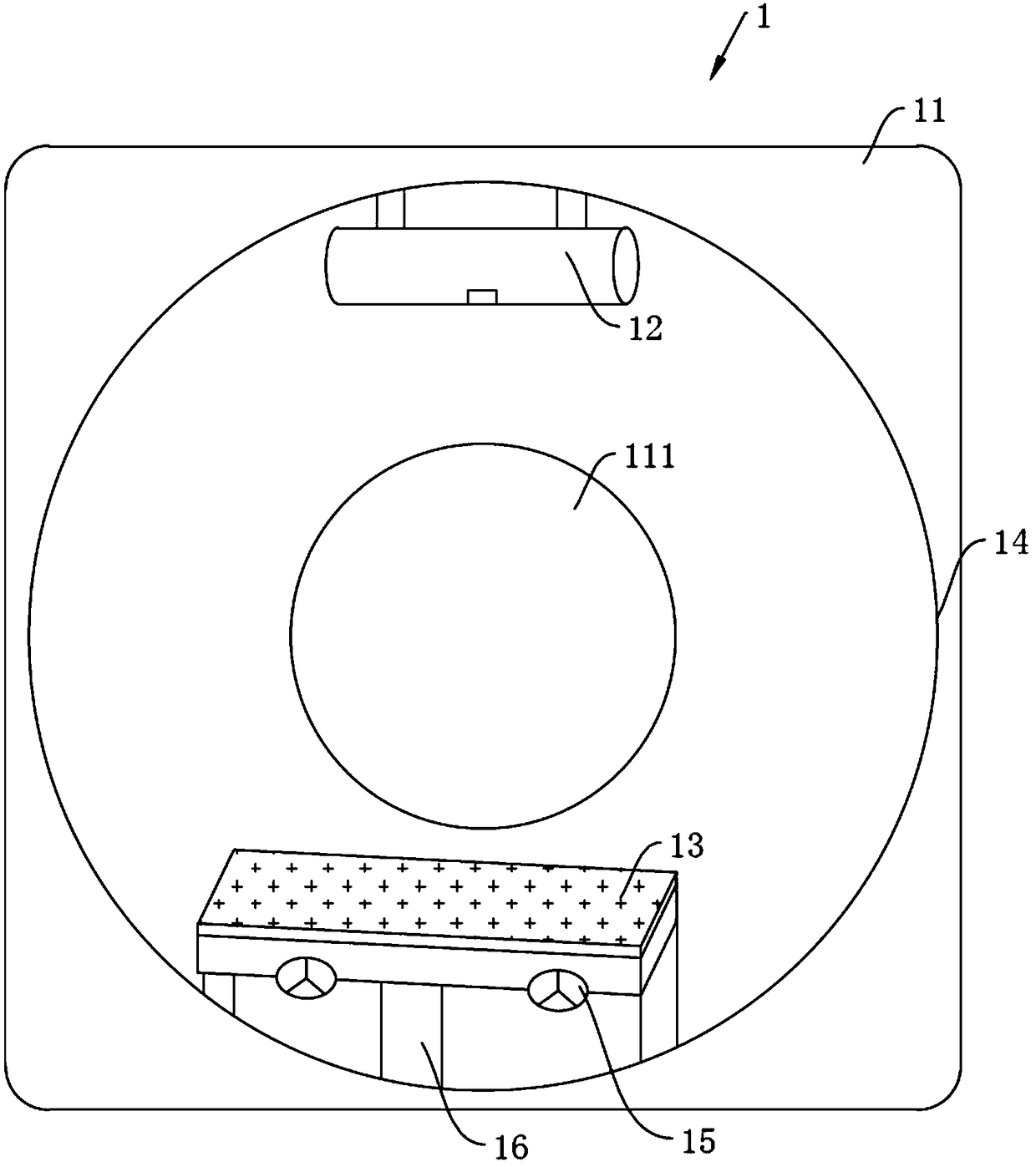
[0037] Such as figure 1 As shown, this embodiment provides a CT scanning frame 1 of a flat-panel CT machine, including a frame 11 , a radiation emitter 12 , a flat-panel detector 13 , a rotating device 14 and a cooling device 15 . The radiation emitter 12 and the flat panel detector 13 are relatively arranged in the rotating device 14, and the rotating device 14 can drive the radiation emitter 12 and the flat panel detector 13 to perform synchronous circular motions relative to the same axis synchronously.

[0038] The scanning frame 1 of the flat-panel CT machine is the main body of the CT machine; the frame 11 is based on the base, and is used to install and carry other components (such as various power boxes, driving motors, wireless transmitting and receiving devices, various cables, rotating Anode starting circuit, KV and mA control circuit, inverter circuit, etc.), and the rotating device 14 is also carried by it. An inner hole 111 is formed on the frame 11 for the entr...


PUM


Abstract

The invention relates to a scanner of a flat panel CT machine. The scanner comprises a frame, a rotating device, a ray emitter and a flat panel detector. The ray emitter and the flat panel detector are oppositely disposed in the rotating device and can be driven by the rotating device to conduct circular motion relative to the same axis synchronously and oppositely. A control circuit of the ray emitter is provided with a pulse modulating circuit, and the ray emission of the ray emitter is controlled by reading pulse signals of the flat panel detector. The reading frequency of the flat panel detector is variable, and ray emission pulse signals and the reading pulse signals of the flat panel detector are consistent in frequency but opposite in phase. The flat panel detector is applied to theCT machine to replace the existing CT detector. The flat panel detector can choose wider width, conducts gap-free scanning, and can ensure no detection missing. When the ray emitter emits rays, the flat panel detector only collects data without reading, and does not emit the rays during reading, trailing and afterglow are avoided, data obtained by the CT machine are more realistic, and images areclearer.

Description

technical field [0001] The invention relates to the field of CT equipment, in particular, to a flat-panel CT machine. Background technique [0002] CT (Computed Tomography), that is, computerized tomography. The basic principle of existing CT imaging is to use X-ray beams to scan a layer of a certain thickness of the human body inspection site. The X-rays that pass through this layer are received by the detector and converted into visible light. The analog / digital converter (analog / digital converter) converts the digital signal into a computer for processing. The processing of image formation is like dividing the selected layer into several cuboids with the same volume, which are called voxels. The scanned information is calculated to obtain the X-ray attenuation coefficient or absorption coefficient of each voxel, and then arranged into a matrix, that is, a digital matrix. Numerical matrices can be stored on disk or CD. Through a digital / analog converter (digital / analog...

Claims


Application Information

Patent Timeline
IPC IPC(8): A61B6/03
CPCA61B6/032
Inventor 刘洪斌
Owner 刘洪斌
Why Eureka
Try Eureka