Improved interlocking tibia intramedullary nail

An intramedullary nail and tibial bone marrow technology, which is applied in the field of orthopedic surgical medical devices, can solve the problems of increasing the damage to the cortical bone in the head area of ​​the locking nail, the high notch of the head of the intramedullary nail, and increasing the operation time. The effect of reducing the risk of bleeding and infection, reducing the risk of intervention, saving operation time

Pending Publication Date: 2019-03-19
KANGHUI MEDICAL INNOVATION
View PDF0 Cites 1 Cited by
  • Summary
  • Abstract
  • Description
  • Claims
  • Application Information

AI Technical Summary

Problems solved by technology

In practical application, the head of this kind of locking nail exposes a lot of bone surface, which is called too high notch. In this case, it will not cause obvious discomfort in the area with thick soft tissue, but if the soft tissue is placed in thinner After tibial intramedullary nailing, too high notch will cause obvious discomfort, which will often irritate the surrounding soft tissues, resulting in discomfort such as bulging, itching, etc.
At present, the only way to avoid excessive notch is to increase the screwing depth clinically, but at the same time, it will also increase the damage to the cortical bone in the head area of ​​the locking screw
In view of this, how to solve the problem of too high notch of the head of the intramedullary nail is a subject to be studied
[0003] In addition, the disadvantage of this type of intramedullary nail is that it is difficult to locate the distal end, and an additional positioning hole must be opened on the bone of the patient's affected limb, which will cause certain trauma to the patient, increase the operation time, and bring the risk of intraoperative bleeding and infection to the patient.

Method used


Image

  • Improved interlocking tibia intramedullary nail
  • Improved interlocking tibia intramedullary nail
  • Improved interlocking tibia intramedullary nail

Examples


Embodiment 1

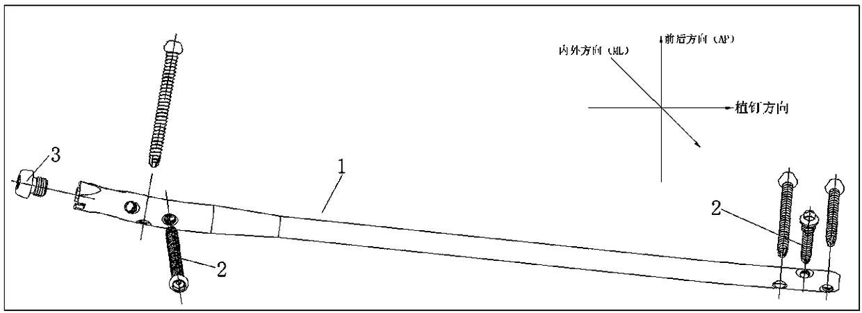
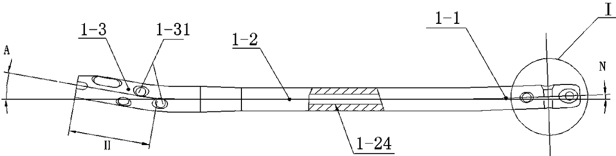
[0094] like figure 1 As shown, an improved interlocking tibial intramedullary nail is inserted into the tibia along the nailing channel, and the design of the distal forward bending zone 1-1 can guide the smooth implantation of the medullary nail along the medullary cavity.

[0095] The middle vertical area 1-2 is the axial load-bearing area of ​​the intramedullary nail. After fracture reconstruction, the axial mechanical demand of the affected limb bone is mainly borne by the middle vertical area.

[0096] Proximal forward bending zone 1-3, the proximal forward bending angle A ranges from 8 degrees to 12 degrees, and the proximal bending distance H ranges within 40mm from the top end surface. The forward bending design meets clinical needs. Choose the necessary design on the tibial anterior condyle surface, do not invade the knee joint cavity, and reduce the impact on the knee joint function.

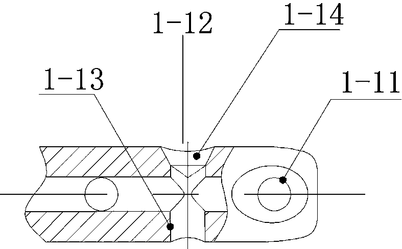
[0097] The first locking nail hole 1-11 at the extreme distal end is 5mm away fro...

Embodiment 2

[0113] like Figure 6 , Figure 7 As shown, after the fixed tail cap is rotated and screwed into the center hole at the top of the main nail, the height H of the exposed part of the tail cap head 3-1 can be used as a supplement to the length of the main nail. Humeral surface fit ( Figure 18 ), to avoid irritation to the surrounding ligaments and surrounding soft tissues, and realize the invention concept of biological low profile. The threaded part 3-2-1 is used to connect the main nail of the intramedullary nail, the lead-in part 3-2-2 plays the role of correcting the thread installation direction, and prevents wrong teeth, and the screwing mechanism 3-4 is used to fix the tail cap and special for surgery The connection area of ​​the tool is mainly used for rotating and screwing in. The structure can be designed as a multi-faceted counterbore such as hexagonal or quincunx. The holding structure 3-6 This mechanism mainly realizes the holding function of the fixed end cap an...

Embodiment 3

[0121] like Figure 8 , Figure 10 , Figure 12 , Figure 15 As shown, the low-profile intramedullary nail locking screw 2 is screwed into the bone surface along the screw implantation channel, and after being compatible with the locking nail hole on the interlocking intramedullary nail (main nail) 1 with a tapered positioning hole at the distal end, Close to the bone surface to complete the implantation. At this time, the height of the exposed part of the locking screw head 2-1 is H. The head of the trapezoidal cylindrical or hemispherical locking screw, and the side close to the bone surface, all adopt a flat design. It can be closely attached to the physiological tibial surface to the maximum extent. Because there is no traditional arc-shaped bottom surface design of the locking nail, the H height of the exposed part has been significantly reduced, and the low-notch effect required by the clinic has been achieved. The height of the head of the locking nail designed with ...


PUM


Abstract

The invention relates to interlocking intramedullary nails, in particular to an improved interlocking tibia intramedullary nail and belongs to the technical field of orthopedic surgery medical instruments. The improved interlocking tibia intramedullary nail comprises an interlocking intramedullary nail of which the distal end is provided with a taper positioning hole, an intramedullary nail lock pin with low notch and an intramedullary nail fixing tail cap with low notch; the interlocking intramedullary nail of which the distal end is provided with a taper positioning hole is composed of threeparts, namely a proximal forerake bending area, a middle vertical area and a distal forerake bending area; a distal interlocking pin hole and a distal taper positioning hole are formed in the distalforerake bending area; the intramedullary nail lock pin with low notch is mounted in a proximal interlocking pin hole and the distal interlocking pin hole of the interlocking intramedullary nail, andcomprises a lock pin head and a threaded rod; the intramedullary nail fixing tail cap with low notch is mounted at the top of the proximal end of the interlocking intramedullary nail of which the distal end is provided with the taper positioning hole, and comprises a tail cap head and a threaded rod.

Description

technical field [0001] The invention discloses an improved interlocking tibial intramedullary nail, which relates to an interlocking intramedullary nail and belongs to the technical field of bone surgery medical instruments. Background technique [0002] Intramedullary nail is a commonly used internal fixation device in orthopedics, mainly used for the treatment of long tubular fractures. The intramedullary nail generally consists of three parts: the main nail, the locking nail and the locking nail. The intramedullary nail locking nail is an important component of the intramedullary nail. During the operation, it passes through both ends of the intramedullary nail along the transverse direction. Its purpose includes two aspects: 1. Prevent the rotation of the fracture end after the intramedullary nail is fixed, and improve the prosthesis. Stability, 2. Fix the fracture block, make the fracture area form temporary stability, facilitate the formation of callus, and play the r...

Claims


Application Information

Patent Timeline
Patent Type & Authority Applications(China)
IPC IPC(8): A61B17/72A61B17/86
CPCA61B17/725A61B17/8605A61B17/8625A61B2017/8655
Inventor 秦宗俊李元勋杨兆权裴磊刘博柯林华
Owner KANGHUI MEDICAL INNOVATION
Why Eureka
Try Eureka