Device and method for cooling desulfurization slurry of thermal power plant

A technology for desulfurization slurry and thermal power plants, applied in the direction of combustion methods, separation methods, chemical instruments and methods, etc., can solve the problems of high investment, low desulfurization efficiency, and inability to achieve deep desulfurization, and achieve the goal of reducing manufacturing costs and improving desulfurization efficiency Effect

Inactive Publication Date: 2019-03-19
李申强
View PDF0 Cites 4 Cited by
  • Summary
  • Abstract
  • Description
  • Claims
  • Application Information

AI Technical Summary

Problems solved by technology

[0002] According to the national air pollution prevention and control plan, the environmental protection policies of some provinces and cities require that the flue gas after desulfurization in thermal power plants be treated with cooling, dehumidification and whitening treatment. Heater cooling, but the cooling layer and desulfurization layer in the existing thermal power plant desulfurization slurry cooling device are concentrated, the desulfurization efficiency is relatively low, and deep desulfurization cannot be realized. At the same time, the size of the slurry heat exchanger is large and the investment is high. It is produced by a full welding process, and the manufacturing cost is high. In addition, because there is no accurate sulfur content detector when the slurry is replaced, it cannot provide data reference for the replacement of the slurry.

Method used


Image

  • Device and method for cooling desulfurization slurry of thermal power plant
  • Device and method for cooling desulfurization slurry of thermal power plant
  • Device and method for cooling desulfurization slurry of thermal power plant

Examples


Embodiment Construction

[0024] The present invention will be further described below in conjunction with accompanying drawing:

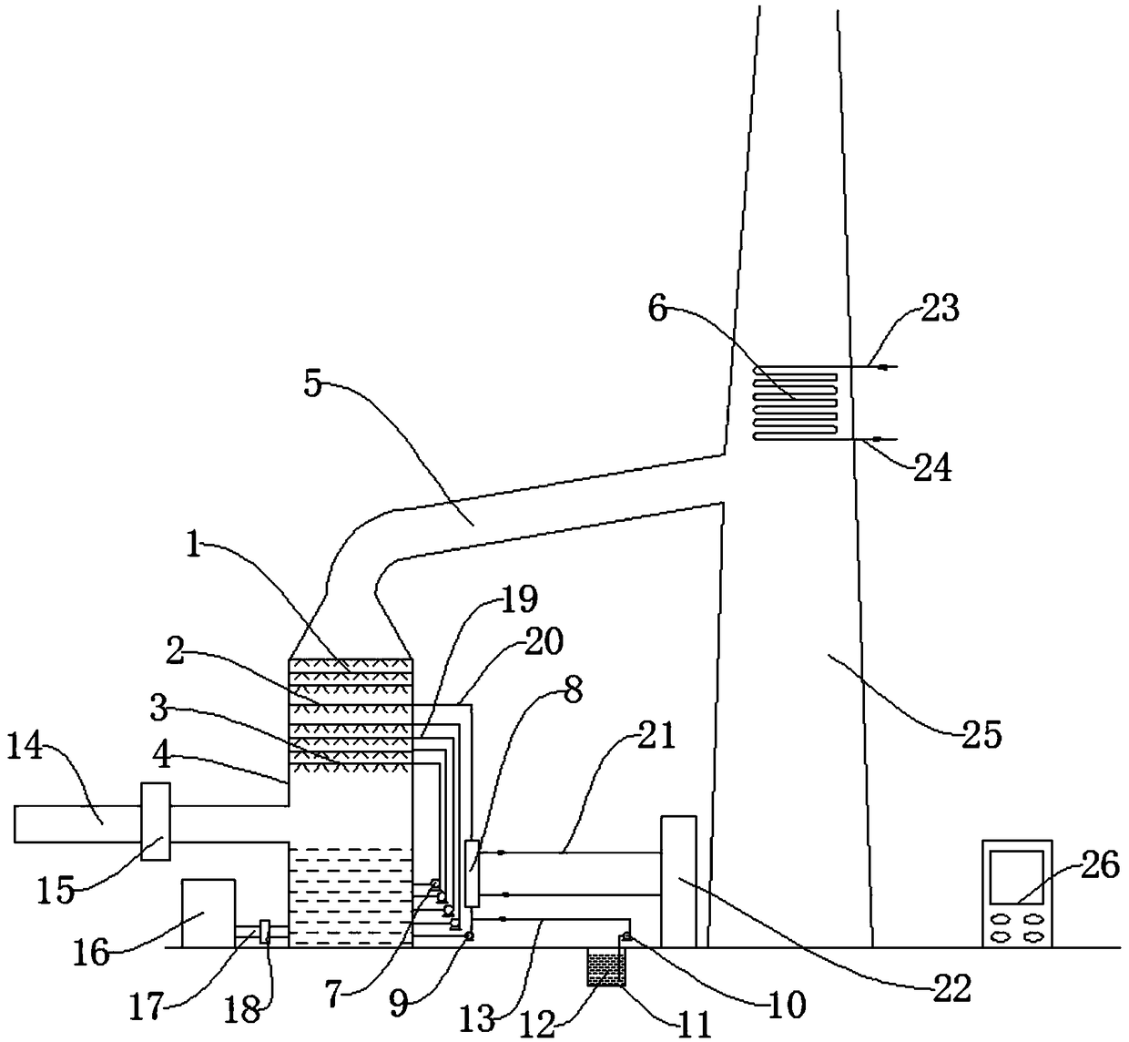
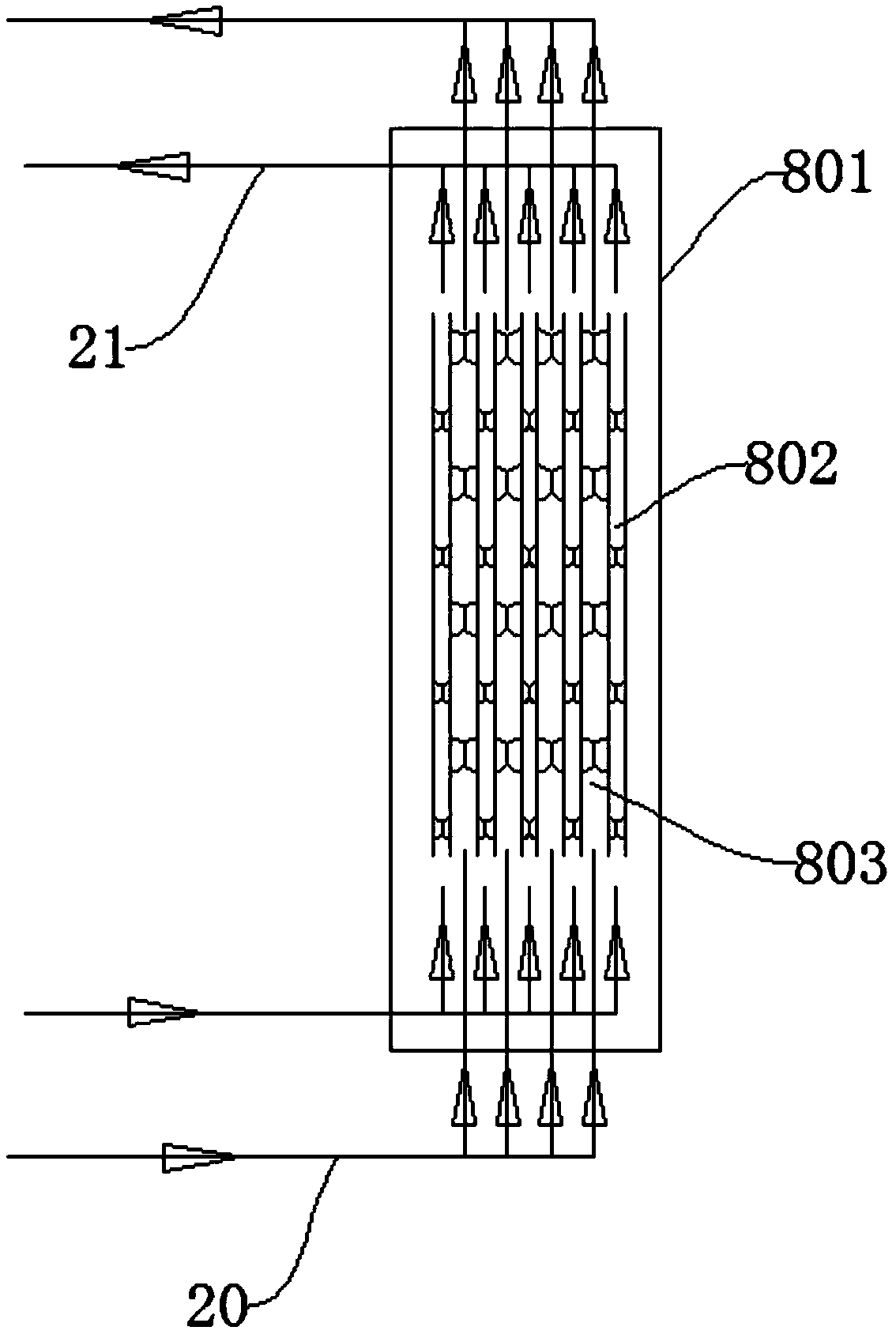
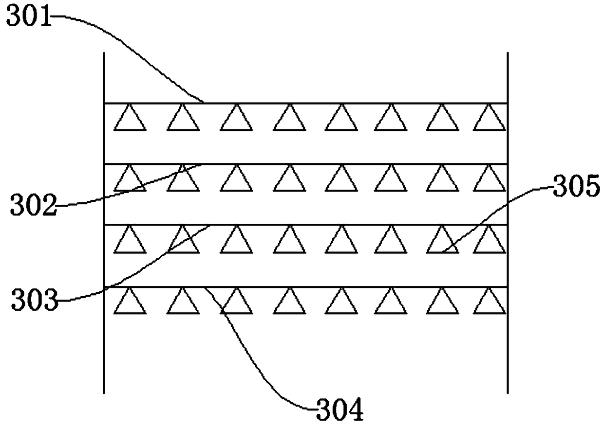
[0025] Such as Figure 1-Figure 4 As shown, a device for cooling desulfurization slurry in a thermal power plant includes a desulfurization tower 4, a desulfurization circulation pump 7, a slurry heat exchanger 8, and an X-ray fluorescence sulfur determination instrument 16. One side of the desulfurization tower 4 is provided with a smoke inlet Pipe 14, the smoke inlet pipe 14 is used to connect with the smoke exhaust pipe of the thermal power plant, the smoke inlet pipe 14 is provided with a smoke inlet control valve 15, and the smoke inlet control valve 15 is used to control the smoke inlet pipe 14, a sulfur content measurement delivery pipe 17 is arranged under the smoke inlet pipe 14, a sulfur content measurement delivery valve 18 is arranged in the middle of the sulfur content measurement delivery pipe 17, and the end of the sulfur content measurement delivery pipe 17 ...


PUM


Abstract

The invention discloses a device and method for cooling desulfurization slurry of a thermal power plant. The device comprises a desulfurization tower, a desulfurization circulating pump, a slurry heatexchanger and an X-ray fluorescent sulfur determination instrument; one side of the desulfurization tower is provided with a smoke inlet pipe; the smoke inlet pipe is provided with a smoke inlet control valve; a sulfur content measuring and conveying pipe is arranged below the smoke inlet pipe; and the middle of the sulfur content measuring and conveying pipe is provided with a sulfur content measuring and conveying valve. The device has the beneficial effects that calcium hydroxide slurry added into a cooling and spraying layer can instantly finish an acid-base reaction with sulfur dioxide in smoke, so that the desulfurization efficiency is increased, and the deep desulfurization operation for the smoke can be finished; meanwhile, due to the adoption of the slurry heat exchanger, all spot-welding processes are omitted and are changed into a surrounding welding process, so that the production cost can be greatly reduced; and due to the arrangement of the X-ray fluorescent sulfur determination instrument, the content of sulfur in the slurry can be precisely detected at fixed time, and thus, precise data reference is provided for slurry replacement.

Description

technical field [0001] The invention relates to the technical field of sulfur slurry cooling devices, in particular to a device and method for cooling desulfurization slurry in thermal power plants. Background technique [0002] According to the national air pollution prevention and control plan, the environmental protection policies of some provinces and cities require that the flue gas after desulfurization in thermal power plants be treated with cooling, dehumidification and whitening treatment. Heater cooling, but the cooling layer and desulfurization layer in the existing thermal power plant desulfurization slurry cooling device are concentrated, the desulfurization efficiency is relatively low, and deep desulfurization cannot be realized. At the same time, the size of the slurry heat exchanger is large and the investment is high. It is produced by an all-welding process, and the manufacturing cost is high. In addition, because there is no accurate sulfur content detect...

Claims


Application Information

Patent Timeline
Patent Type & Authority Applications(China)
IPC IPC(8): B01D53/80B01D53/50B01D53/48B01D53/96F23J15/04F23J15/06F23J15/08
CPCB01D53/343B01D53/48B01D53/502B01D53/80B01D53/96B01D2251/404B01D2258/0283F23J15/04F23J15/06F23J15/08F23J2215/20Y02E20/30
Inventor 李申强姜士平王巍付青梅李芷冰李芷蓓
Owner 李申强
Why Eureka
Try Eureka