
T-shaped self-support structure suitable for curved surface friction stir welding

A self-supporting structure, friction stir technology, applied in welding equipment, non-electric welding equipment, edge parts of workpieces, etc., can solve the problem of inability to ensure the gap between two curved surfaces and the amount of misalignment, and can reduce the gap between assembly and fit , The effect of improving production efficiency and saving materials

Inactive Publication Date: 2019-03-19
CRRC CHANGCHUN RAILWAY VEHICLES CO LTD
View PDF5 Cites 2 Cited by
  • Summary
  • Abstract
  • Description
  • Claims
  • Application Information

AI Technical Summary

Problems solved by technology

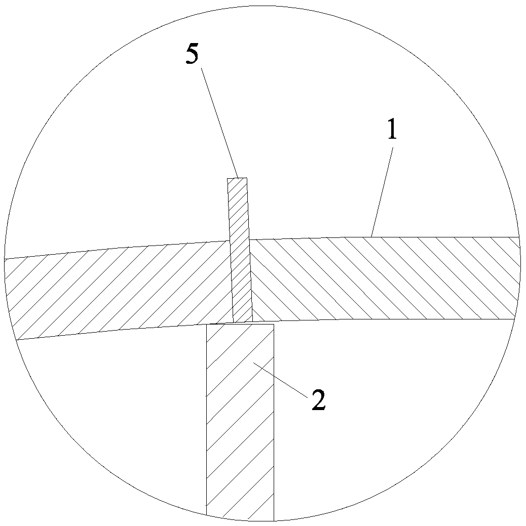
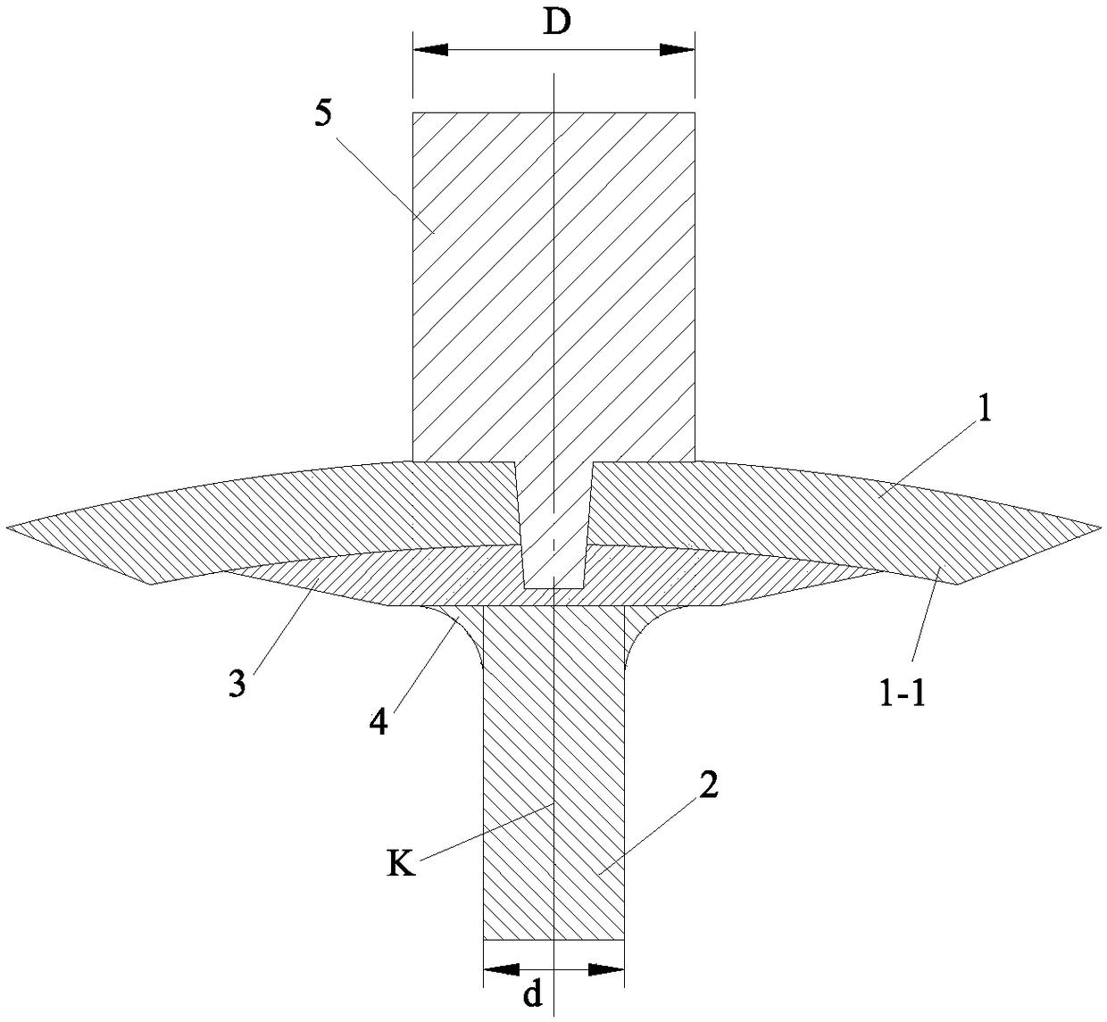
[0006] In order to solve the technical problem that friction stir welding cannot be used for welding curved surface skin panels due to the inability to ensure the assembly gap and misalignment of the two curved surfaces during the welding process, the present invention provides a T-type automatic welding machine suitable for curved surface friction stir welding. supporting structure

Method used


Image

  • T-shaped self-support structure suitable for curved surface friction stir welding
  • T-shaped self-support structure suitable for curved surface friction stir welding

Examples


Embodiment Construction

[0012] The present invention will be described in further detail below in conjunction with the accompanying drawings.

[0013] Such as figure 1 and figure 2 As shown, the T-shaped self-supporting structure suitable for curved surface friction stir welding in the present invention includes: a rib plate 2, a profiled curved panel 3 and two chamfers 4, the curvature of the profiled curved panel 3 and the curvature of the curved skin panel 1 Equal, the width of the profiled curved panel 3 is greater than or equal to the shoulder diameter D of the stirring head 5, the length of the profiled curved panel 3 is equal to the length of the curved surface skin panel 1; the top end surface of the rib plate 2 is fixed on the profiled curved panel 3, and the extension line K of the central line of the rib plate 2 passes through the highest point of the profiled curved panel 3; two chamfers 4 are fixed at the connection position between the rib plate 2 and the profiled curved panel 3, and ...


PUM


Abstract

The invention discloses a T-shaped self-support structure suitable for curved surface friction stir welding, and relates to the technical field of friction stir welding of curved surface metal structures. The structure comprises a ribbed plate, a profile curved surface plate and two chamfering angles; the curvature and the length of the profile curved surface plate are the same with the curvatureand the length of a curved surface cover plate; the width of the profile curved surface plate is higher than and equal to the shaft shoulder diameter D of a stirring head; the top end surface of the ribbed plate is fixedly connected to the inner side concave surface of the profile curved surface plate; the extension line of the center line of the ribbed plate passes through the highest point of the profile curved surface plate; the two chamfering angles are both fixedly connected with the ribbed plate and the profile curved surface plate; and the radiuses (FORMULA) d of the chamfering angles are the thickness of the ribbed plate. The profile curved surface plate fitted with the inner side concave surface of the curved surface cover plate and the chamfering angles are additionally providedon the ribbed plate, so that assembly fit gaps are greatly reduced; and through the chamfering angles, enough materials are supported under a shaft shoulder of the stirring head in the welding process, the axial top forging force can be smoothly transferred to the ribbed plate during welding, and the complexity of needing additional tools to support the back part under the shaft shoulder is prevented.

Description

technical field [0001] The invention relates to the technical field of friction stir welding of curved metal structures, in particular to a T-shaped self-supporting structure suitable for friction stir welding of curved surfaces. Background technique [0002] As a solid-phase welding method, friction stir welding (FSW) has the advantages of beautiful appearance of welded joints, good comprehensive mechanical properties, small welding deformation, environmental protection and no need to add welding materials. It is suitable for aluminum alloys, magnesium alloys, titanium alloys, Copper alloy and other metal materials are welded, so friction stir welding has been widely promoted and applied in the fields of shipbuilding, aviation, aerospace and rail transit. [0003] In the welding of curved T-joints, the fusion welding double-sided fillet joint technology currently used has poor joint formation and low performance, which cannot meet the needs of car body connections. [0004...

Claims


Application Information

Patent Timeline
Patent Type & Authority Applications(China)
IPC IPC(8): B23K33/00B23K20/12
CPCB23K20/127B23K33/00
Inventor 刘杰何广忠闫占奇李文晓
Owner CRRC CHANGCHUN RAILWAY VEHICLES CO LTD
Learn More