
Quartz stone panel molding press

A technology for quartz stone plates and presses, which is applied to forming indenters, ceramic forming machines, and auxiliary forming equipment. Vacuuming time, achieving tightness, reducing impact

Pending Publication Date: 2019-03-19
肇庆威尼托机械有限公司
View PDF1 Cites 0 Cited by
  • Summary
  • Abstract
  • Description
  • Claims
  • Application Information

AI Technical Summary

Problems solved by technology

The outer cover in the above scheme covers all the indenters, and the vibrating body on the indenter vibrates in the cover. The space is too large, and it takes too long to vacuumize, and it is not conducive to the heat dissipation of the vibrating body, and it is easy to burn out.
[0003] Soon the internal vibrating press was replaced by the external vibrating press. Due to the soft connection between the indenter and the outer frame in the external vibrating press on the market, the indenter jumps violently during work, which is likely to cause the indenter to break out. Rubbing back and forth, left and right, crepe the paper separating the slab from the vibrating head and sink into the slab. The depth of the sinking has to be removed by processing; and the higher the vibration frequency of the vibrating body on the indenter, the more the indenter jumps upwards. The larger the amplitude, the current equipment manufacturers usually add a limit hydraulic cylinder or cylinder on the upper part of the vibrating head, which acts as a one-way support for the vibrating head, preventing the vibrating head from jumping too high. Or the solid state limitation of the cylinder, which greatly reduces the vibration force of the vibrating head, so that the vibration time of the vibrating head needs to be increased to ensure the quality of the product, which greatly affects the production efficiency of quartz stone plate pressing

Method used


Image

  • Quartz stone panel molding press
  • Quartz stone panel molding press
  • Quartz stone panel molding press

Examples


Embodiment Construction

[0024] In order to make the technical problems, technical solutions and beneficial effects solved by the present invention clearer, the present invention will be further described below in conjunction with the accompanying drawings and embodiments.

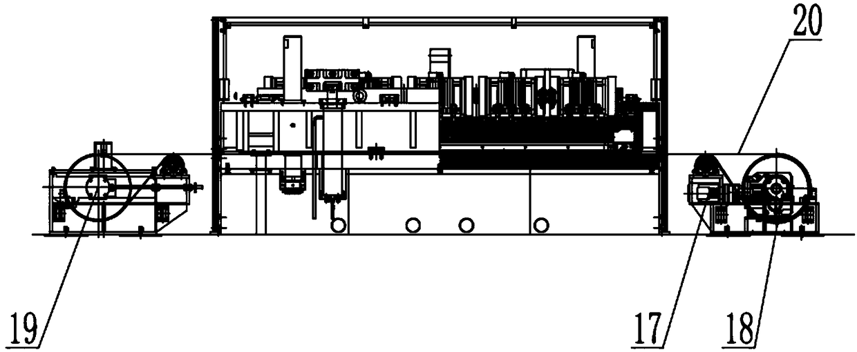
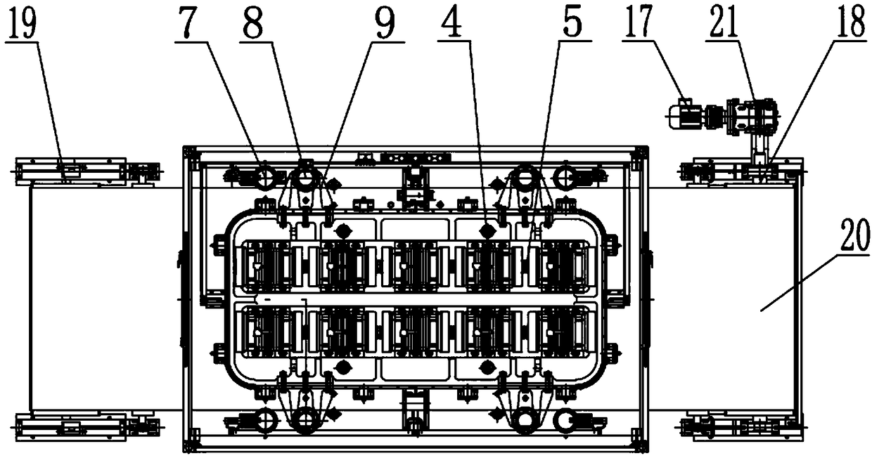
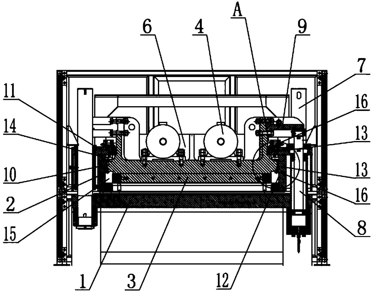
[0025] Such as Figure 1-4 As shown, a quartz stone slab forming press of the present invention includes a machine base 1, an outer cover 2, a punch 3 and a vibrating mechanism. Head 3 suffered interface fracture during strenuous exercise. The vibrating mechanism is two sets of vibrating units with opposite directions, and each vibrating unit includes a plurality of vibrating motors 4 connected in series by couplings 5, and the exciting force can reach 120KN. The punch 3 is provided with a concave cavity 6, and the vibration mechanism is located in the concave cavity 6. There are 4 sets of guide columns 7 and hydraulic cylinders 8 on the base 1, and the punch 3 moves upward along the guide columns 7 under the action of the hydrau...


PUM


Abstract

The invention relates to the technical field of panel molding equipment and in particular discloses a quartz stone panel molding press. The quartz stone panel molding press comprises a base, an outercover, a punch and a vibrating mechanism. The punch is provided with a cavity, the vibrating mechanism is located in the cavity, a guide pillar and a hydraulic cylinder are arranged on the base, and the punch moves upward along the guide pillar under the action of the hydraulic cylinder. The quartz stone panel molding press is characterized in that a lifting connecting seat is fixedly arranged onthe outer side of the punch, the hydraulic cylinder is located at the bottom of the lifting connecting seat, the punch is formed integrally, an annular bump is arranged on the outer wall of the punch,an inner enclosure in contact with the punch is arranged at the upper end of the outer cover, the annular bump is located below the inner enclosure, a wear-resistant layer coats the inner wall of theouter cover, sealing parts are mounted between the punch and the outer cover and between the punch and the inner enclosure, so that the outer cover and the punch are assembled to form a sealed chamber, and the chamber is divided into an upper high pressure chamber and a lower vacuum chamber which are sealed through the annular bump. The quartz stone panel molding press not only shortens the vacuumizing working time, but also improves the production efficiency of pressing and molding the quartz stone panels.

Description

technical field [0001] The invention relates to the technical field of plate forming equipment, in particular to a quartz stone plate forming press. Background technique [0002] At present, the molding presses for quartz stone slabs on the market are initially of the internal vibration type. Please refer to the Chinese Utility Model Authorized Patent, the authorized announcement number is CN201446616U, and the authorized announcement date is May 5, 2010. The vacuum vibration forming press of the present invention includes a press composed of a machine base and a frame, and a feeding device composed of a mold frame and a belt. It is characterized in that a vacuum vibration device is provided on the frame, and the vacuum vibration device includes: a ring The vacuum cover set around the frame, the pressure head matching the inner cavity size of the vacuum cover, and the hydraulically controlled power cylinder installed on the frame to make the vacuum cover and the pressure hea...

Claims


Application Information

Patent Timeline
Patent Type & Authority Applications(China)
IPC IPC(8): B28B3/04B28B17/00
CPCB28B3/022B28B3/04B28B17/00
Inventor 苏连华朱维俊
Owner 肇庆威尼托机械有限公司
Learn More