Centralized heat supply system and method

A technology of central heating and heat exchange system, applied in hot water central heating system, heating system, heating method, etc., can solve the problems such as inability to carry out, difficult to withstand the temperature and pressure of high temperature hot water, poor matching, etc.

Active Publication Date: 2019-03-19
北京热科能源技术研究有限公司
View PDF11 Cites 6 Cited by
  • Summary
  • Abstract
  • Description
  • Claims
  • Application Information

AI Technical Summary

Problems solved by technology

[0004] However, since the heating pipe network in the urban area of ​​most northern cities in China is formed on the basis of years of continuous construction, it is subject to many constraints such as the construction environment, cost, and city appearance, and the old heating pipe network in the urban area has been renovated. There is a lot of resistance, and in many cases it is even impossible
During the popularization and application of this central heating technology with large temperature difference in heating cities in the north, the problem of poor matching between the existing heating pipe network

Method used


Image

  • Centralized heat supply system and method
  • Centralized heat supply system and method
  • Centralized heat supply system and method

Examples


Embodiment 1

[0062] Embodiment 1: A central heating system

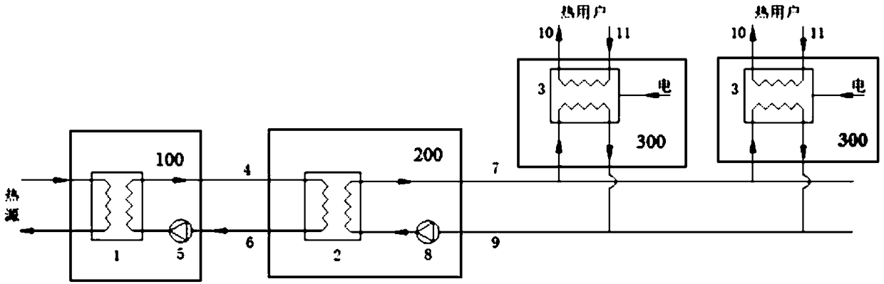
[0063] Generally speaking, central heating system of the present invention such as figure 1 and Figure 5 As shown, the central heating system includes a heat source heat exchange system 100, multiple absorption heat exchange systems 200 and multiple compression heat exchange systems 300, and the heat release side of the heat source heat exchange system 100 is used to communicate with the heat supply of the heat source The medium inlet and outlet pipes; the heat-taking side of the heat source heat exchange system 100 and the heat-releasing side of the absorption heat exchange system 200 are connected through the primary network water supply pipe 4 and the primary network return water pipe 6; the absorption heat exchange system 200 The heat extraction side and the heat release side of the compression heat exchange system 300 are connected through the secondary network water supply pipeline 7 and the secondary network return water...

Embodiment 2

[0084] Embodiment 2: Central heating system different from the heat source heat exchange device in Embodiment 1

[0085] On the basis of Example 1, the heat source heat exchange device 1 of the central heating system provided by this example is as follows: Figure 6 and Figure 7 As shown, the heat source heat exchange device 1 includes N steam turbine condensers 15-1, 15-2, ... 15-N and a second peak regulation heater 16, N steam turbine condensers 15-1, 15-2, ... 15-N are connected in series through pipelines from front to back, the water inlet of the steam turbine condenser 15-N at the end is connected with the water outlet of the first circulation pump 5, and the water outlet of the steam turbine condenser 15-1 at the front is connected with the water outlet of the first circulating pump 5 The water inlet of the second peak regulation heater 16 is connected, and the water outlet of the second peak regulation heater 16 is connected with the water inlet of the primary netwo...

Embodiment 3

[0091] Embodiment 3, a kind of central heating method

[0092] Adopt the centralized heating system that above-mentioned embodiment 1 or embodiment 2 provide, as figure 1 As shown, the central heating method generally includes the following steps:

[0093] Step A: exchanging heat between the heat source medium and the primary net water;

[0094] Step B: Circulate the network water once;

[0095] Step C: exchanging heat between the primary mesh water and the secondary mesh water;

[0096] Step D: Circulating secondary network water;

[0097] Step E: exchanging heat between the secondary mesh water and the tertiary mesh water;

[0098] Step F: Perform three network water supply and return water.

[0099] Specifically, step A includes the following steps:

[0100] Step A1: The inlet of the heat release side of the heat source heat exchange device 1 receives the heat source heating medium transported by the heat supply pipeline of the heat source, and transmits the heat ener...


PUM


Abstract

The invention discloses a centralized heat supply system and method. The centralized heat supply system comprises one or more heat source heat-exchange systems, one or more absorption heat-exchange systems and one or more compression heat-exchange systems. The centralized heat supply method comprises the steps of heat exchange between a heat source heat-supply medium and primary network water, circulation of the primary network water, heat exchange between the primary network water and secondary network water, circulation of the secondary network water, heat exchange between the secondary network water and tertiary network water, water supply and return of a tertiary network and the like. According to the centralized heat supply system and method, compared with an existing large-temperature-difference centralized heat supply mode, the heat supply capacity of a secondary network water supply pipelines is kept under the precise of not increasing the supplied water temperature and pressure of an old heat supply pipe network in an urban district and not affecting the heat delivery capacity of the heat supply network in the urban district, and thus the transformation cost of the existing pipeline network is saved.

Description

technical field [0001] The invention relates to heating engineering technology in the field of energy, in particular to a central heating system and a central heating method thereof. Background technique [0002] Due to the rapid development of urbanization, the continuous expansion of urban scale, and the continuous improvement of urban environmental protection awareness, the heating mode of regional boiler rooms or small thermal power plants can no longer meet the needs of the growing urban centralized heating area. Urban heating The model is gradually developing towards the method of using large-scale thermal power plants as the heat source for central heating. However, due to the limited steam extraction and heat supply capacity of thermal power plants, even under the condition of steam extraction and heat supply, there is still a large amount of exhaust steam discharged at the end of the steam turbine, and a large amount of exhaust steam condensation waste heat is disch...

Claims


Application Information

Patent Timeline
IPC IPC(8): F24D3/18F24D3/02F24D19/10
CPCF24D3/02F24D3/18F24D19/1039
Inventor 张世钢
Owner 北京热科能源技术研究有限公司
Why Eureka
Try Eureka