Passivation-contact-based floating-junction back-passivation crystalline silicon battery and preparation method thereof

A technology of backside passivation and crystalline silicon cells, which is applied in the direction of circuits, photovoltaic power generation, electrical components, etc., can solve the problems of floating junction passivation effect, amorphous silicon damage, etc., to improve passivation effect, reduce impact, avoid The effect of leakage

Pending Publication Date: 2019-03-19
SUZHOU TALESUN SOLAR TECH CO LTD +1
View PDF0 Cites 0 Cited by
  • Summary
  • Abstract
  • Description
  • Claims
  • Application Information

AI Technical Summary

Problems solved by technology

[0003] At present, some existing crystalline silicon cells use floating junctions based on amorphous silicon / crystalline silicon heterojunctions for back passivation. However, since the heat treatment temperature of amorphous silicon generally cannot The sintering temperature required for the preparation of metal electrodes by screen printing is generally around 780°C. Therefore, when the floating junction based on amorphous silicon / crystalline silicon heterojunction is used for rear passivation, the high temperature sintering process will Cause some damage to amorphous silicon, which will have a certain impact on the passivation effect of the floating junction

Method used


Image

  • Passivation-contact-based floating-junction back-passivation crystalline silicon battery and preparation method thereof
  • Passivation-contact-based floating-junction back-passivation crystalline silicon battery and preparation method thereof
  • Passivation-contact-based floating-junction back-passivation crystalline silicon battery and preparation method thereof

Examples


Embodiment Construction

[0032] The following will clearly and completely describe the technical solutions in the embodiments of the present invention with reference to the accompanying drawings in the embodiments of the present invention. Obviously, the described embodiments are only some, not all, embodiments of the present invention. Based on the embodiments of the present invention, all other embodiments obtained by persons of ordinary skill in the art without making creative efforts belong to the protection scope of the present invention.

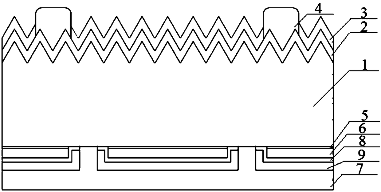
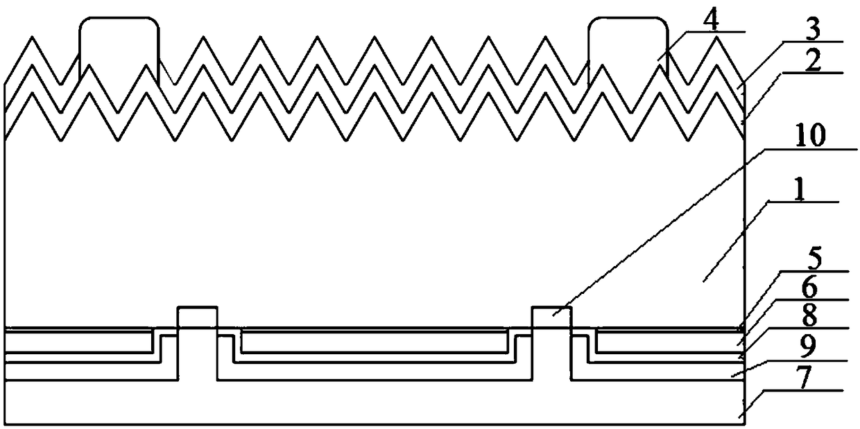
[0033] See figure 1 , which shows a schematic structural view of a passivated contact-based floating junction rear passivated crystalline silicon cell provided by an embodiment of the present invention, which may include a p-type silicon substrate 1 and a tunnel oxide layer located on the back of the p-type silicon substrate 1 5. The n-type polysilicon layer 6 located on the back of the tunneling oxide layer 5, the tunneling oxide layer 5 and the n-type polysi...


PUM

PropertyMeasurementUnit
thicknessaaaaaaaaaa
thicknessaaaaaaaaaa
thicknessaaaaaaaaaa

Abstract

The invention discloses a passivation-contact-based floating-junction back-passivation crystalline silicon battery and a preparation method thereof. The crystalline silicon battery comprises a p typesilicon substrate, a tunneling oxide layer form on the back surface of the p type silicon substrate, and an n type polysilicon layer formed on the back surface of the tunneling oxide layer. The tunneling oxide layer and the n type polysilicon layer form a floating junction; and an open hole is formed in a preset position of the floating junction. In addition, the crystalline silicon battery also includes a metal electrode that is formed on the back surface of the n type polysilicon layer and is in contact with the exposed p type silicon substrate through the open hole and a first dielectric layer that is arranged between the n type polysilicon layer and the metal electrode in the open hole. According to the invention, since the tunneling oxide layer and the n type polysilicon layer can beresistant to the high temperature in metal electrode preparation without any change and can be protected from being damaged by the high temperature, the influence on the floating junction by the high-temperature sintering process is eliminated, so that the passivation effect on the crystalline silicon battery by the floating junction is improved.

Description

technical field [0001] The invention relates to the technical field of passivation of solar cells, and more specifically relates to a passivation contact-based floating junction rear passivation crystalline silicon cell and a preparation method thereof. Background technique [0002] Photovoltaic power generation has been widely used due to its renewability, cleanliness, and easy access. Among them, solar cells, which are the core components of photovoltaic power generation, have also become a hot research topic. At present, solar cells are still dominated by crystalline silicon cells. In order to improve the photoelectric conversion efficiency of crystalline silicon cells, it is often necessary to process them. Among them, back passivation is one of the important methods to improve the photoelectric conversion efficiency of crystalline silicon cells. According to a crystalline silicon battery using a floating junction for rear passivation reported by the University of New S...

Claims


Application Information

Patent Timeline
Patent Type & Authority Applications(China)
IPC IPC(8): H01L31/0747H01L31/0216H01L31/0352H01L31/20
CPCH01L31/02168H01L31/035281H01L31/0747H01L31/202Y02E10/50Y02P70/50
Inventor 张树德魏青竹倪志春钱洪强连维飞胡党平王泽辉
Owner SUZHOU TALESUN SOLAR TECH CO LTD
Why Eureka
Try Eureka