System and method for removing CO (carbon monoxide) in hydrogen gas of proton exchange membrane fuel battery

A proton exchange membrane and fuel cell technology, applied in fuel cells, electrical components, separation methods, etc., can solve problems such as excessive CO content, and achieve the effect of reducing performance and service life

Pending Publication Date: 2019-03-22
SOUTHWEST RES & DESIGN INST OF CHEM IND
View PDF15 Cites 12 Cited by
  • Summary
  • Abstract
  • Description
  • Claims
  • Application Information

AI Technical Summary

Problems solved by technology

[0007] The object of the present invention is to provide a system and method for removing CO from hydrogen used in proton exchange membrane fuel cells to solve the problem of excessive CO content in hydrogen used in existing fuel cells

Method used


Image

  • System and method for removing CO (carbon monoxide) in hydrogen gas of proton exchange membrane fuel battery
  • System and method for removing CO (carbon monoxide) in hydrogen gas of proton exchange membrane fuel battery
  • System and method for removing CO (carbon monoxide) in hydrogen gas of proton exchange membrane fuel battery

Examples


Embodiment 1

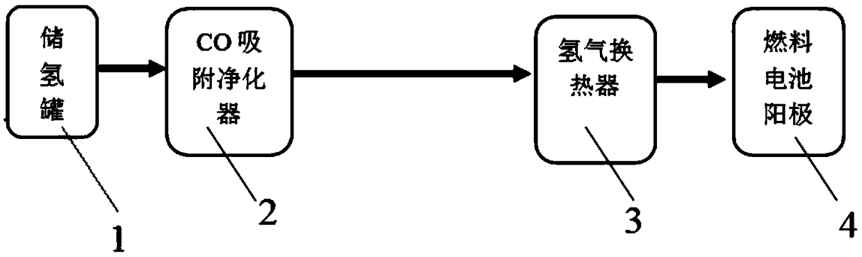
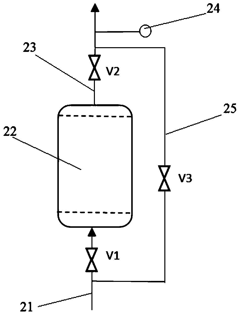
[0033] A CO removal system supporting a 1kW hydrogen fuel cell is as follows: figure 1 and figure 2 shown. The system includes a hydrogen storage tank 1, a CO adsorption purifier 2, a hydrogen heat exchanger 3, and a fuel cell anode 4 connected in sequence, wherein the CO adsorption purifier 2 includes a hydrogen inlet pipeline 21, an inlet pipeline control valve V1, an adsorption device 22, a purified hydrogen outlet pipeline 23, an outlet pipeline control valve V2 and a CO detection probe 24 located on the purified hydrogen outlet pipeline 23, the hydrogen inlet pipeline 21 communicates with the inlet of the hydrogen storage tank 1 and the adsorber 22, and the purified hydrogen outlet The pipeline 23 communicates with the outlet of the adsorber 22 and the hydrogen heat exchanger 3. The adsorber 22 is filled with an activated carbon-loaded copper adsorbent with a volume of 0.2 liters. Bypass line 25 for valve V3.

[0034] When working, open the control valves V1 and V2, c...

Embodiment 2

[0036] A CO removal system supporting a 30kW hydrogen fuel cell is as follows: figure 1 and figure 2 shown. It consists of an adsorber and related devices. The adsorber is filled with X-type molecular sieve-loaded copper adsorbent with a volume of 5 liters. The CO removal system and hydrogen purification process and operation steps are the same as in Example 1.

Embodiment 3

[0038] The CO removal system for a 300kW hydrogen fuel cell is as follows: figure 1 and figure 2 shown. It consists of an adsorber and related devices. The adsorber is filled with MCM mesoporous material-loaded copper adsorbent with a volume of 100 liters. The CO removal system and hydrogen purification process and operation steps are the same as in Example 1.


PUM

PropertyMeasurementUnit
adsorption capacityaaaaaaaaaa

Abstract

The invention provides a system for removing CO (carbon monoxide) in hydrogen gas of a proton exchange membrane fuel battery, and belongs to the technical field of purification of hydrogen gas. The system comprises a hydrogen storage tank, a CO adsorption purifier, a hydrogen gas heat exchanger and an anode of a fuel battery which are sequentially communicated, wherein the CO adsorption purifier comprises a hydrogen gas inlet pipeline, a control valve of the inlet pipeline, at least one adsorber, a purified hydrogen gas outlet pipeline, a control valve of the outlet pipeline, and a CO detection probe, and the CO detection probe is positioned on the purified hydrogen gas outlet pipeline; the hydrogen gas inlet pipeline is communicated with the hydrogen storage tank and an inlet of each adsorber, the purified hydrogen gas outlet pipeline is communicated with an outlet of each adsorber and the hydrogen gas heat exchanger, and each adsorber is internally filled with a CO adsorbent. The invention also provides a method for removing the CO by the removal system. After the CO is adsorbed by the system, the volume fraction of CO in the hydrogen gas entering the anode of the fuel battery iscontrolled to be lower than 0.2mumol / mol, and the CO in the hydrogen gas is prevented from entering the anode of the fuel battery and degrading the property and service life of the noble metal catalyst.

Description

technical field [0001] The invention belongs to the technical field of fuel cell hydrogen purification, in particular to a system and method for removing CO from hydrogen used in proton exchange membrane fuel cells. Background technique [0002] Proton exchange membrane fuel cell (PEMFC) has the advantages of high power generation efficiency, environmental friendliness, and wide range of hydrogen fuel sources. It has broad application prospects in fixed power stations, vehicle power supplies, portable power supplies, aerospace and other fields, and has been highly valued by governments around the world. . At present, one of the important factors affecting the commercialization of proton exchange membrane fuel cells is the poisoning and failure of catalysts. A small amount of CO impurities in hydrogen fuel can lead to a significant reduction in the activity of platinum, palladium and other noble metal catalysts, and even completely lose their activity in severe cases. [000...

Claims


Application Information

Patent Timeline
Patent Type & Authority Applications(China)
IPC IPC(8): B01D53/04H01M8/0668
CPCB01D53/04H01M8/0668B01D2259/40086B01D2257/502B01D2256/16Y02E60/50
Inventor 管英富张剑锋杨云何秀容陶宇鹏刘晓阳张汇霞
Owner SOUTHWEST RES & DESIGN INST OF CHEM IND
Why Eureka
Try Eureka