In-situ dimensional measurement method and device for parts

A technology for measuring devices and parts, which is applied in the direction of measuring devices, optical devices, instruments, etc., can solve the problems of unrealistic measurement, low efficiency of contact method, and difficulty in guaranteeing processing accuracy, etc., to achieve easy system maintenance and upgrade, and small imaging distortion , Improve the effect of integration

Inactive Publication Date: 2019-03-22
BEIJING INST OF AEROSPACE CONTROL DEVICES
View PDF8 Cites 1 Cited by
  • Summary
  • Abstract
  • Description
  • Claims
  • Application Information

AI Technical Summary

Problems solved by technology

[0002] In the fields of aerospace, precision machining, automated production lines, metrology and testing, etc., it is often necessary to in-situ (or online) detection or real-time monitoring of key dimensions and shape tolerances of parts, such as diameter, length, coaxiality, and even Deformation and other important parameters meet the requirements of precision machining for detection, avoiding inconsistent machining before and after due to multiple disassembly of parts and manual interference, and it is difficult to guarantee the final machining accuracy
At present, the existing in-situ detection methods are mainly mechanical contact methods, and the contact method has low efficiency, low degree of automation, and is easily affected by manual operation and actual processing environment, and the accuracy is difficult to guarantee, especially in complex airtight Measurements may not be possible in processing environments

Method used


Image

  • In-situ dimensional measurement method and device for parts
  • In-situ dimensional measurement method and device for parts
  • In-situ dimensional measurement method and device for parts

Examples


Embodiment

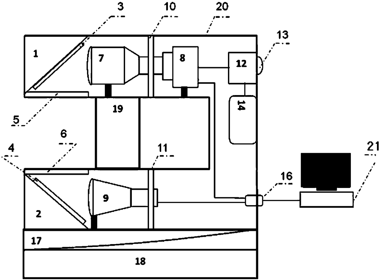
[0045] The composition of an in-situ size measuring device for parts includes: mirror frame A1, mirror frame B2, mirror A3, mirror B4, glass sheet A5, glass sheet B6, telecentric lens 7, image sensor 8, telecentric light source 9. Isolation frame A10, isolation frame B11, trigger controller 12, trigger button 13, battery 14, electrical interface 16, pitch and yaw adjustment platform 17, vertical translation platform 18, support column 19, equipment housing 20 and computer 21, The installation and position relationship of the above components are as follows:

[0046] Reflector A3 and reflector B4 are respectively installed on reflector frame A1 and reflector frame B2, the reflectivity of reflector A3 and reflector B4 is 90%, and the angle adjustment range of reflector frame A1 and reflector frame B2 is ±3°, the minimum adjustment angle is 1', with locking function, mirror frame A1, mirror frame B2, glass sheet A5, glass sheet B6, telecentric lens 7, image sensor 8, telecentric ...


PUM

PropertyMeasurementUnit
Diameteraaaaaaaaaa

Abstract

An in-situ dimensional measurement method and device for parts are provided. The device herein comprises a mechanical portion, an optical imaging portion, an image acquisition portion and an image processing portion; the mechanical portion is composed of a pair of reflector carriers, a pair of isolators, a pitching and yawing adjustment platform, a vertical shift platform, a support post, and a device housing. The optical imaging portion is composed of a pair of reflectors, a pair of filters, a telecentric lens and a telecentric light source. The image acquisition portion is composed of an image sensor, a trigger controller, a trigger button, a battery and a USB (universal serial bus) interface. The image processing portion is composed of a computer and image processing software. The method herein is based on machine vision provides in-situ dimensional measurement for small parts; removing a part under measurement from a work station is not required during measuring; the part under measurement is irradiated with the telecentric source; the image sensor acquires an image that is processed by the image processing software; dimensional information of the part can be calculated. The device and method herein have the advantages of zero contact, high efficiency, high precision, automated measurement and the like.

Description

technical field [0001] The invention relates to a method and a device for measuring in-situ dimensions of parts, belonging to the technical field of on-line measurement. Background technique [0002] In the fields of aerospace, precision machining, automated production lines, metrology and testing, etc., it is often necessary to in-situ (or online) detection or real-time monitoring of key dimensions and shape tolerances of parts, such as diameter, length, coaxiality, and even Important parameters such as deformation can meet the requirements of precision machining for detection, and avoid the inconsistency of front and rear machining due to multiple disassembly of parts and manual interference, making it difficult to guarantee the final machining accuracy. At present, the existing in-situ detection methods are mainly mechanical contact methods, and the contact method has low efficiency, low degree of automation, and is easily affected by manual operation and actual processin...

Claims


Application Information

Patent Timeline
IPC IPC(8): G01B11/02G01B11/08G01B11/27G01B11/16
CPCG01B11/02G01B11/08G01B11/16G01B11/27
Inventor 惠宏超魏东辰何江涛
Owner BEIJING INST OF AEROSPACE CONTROL DEVICES
Why Eureka
Try Eureka