Method and device for diagnosing defects of laser additive manufacturing
A technology of laser material addition and defect diagnosis, which is applied in the direction of measuring devices, material analysis and material analysis through optical means, can solve problems such as defect diagnosis, and achieve the effect of stable diagnosis and monitoring
- Summary
- Abstract
- Description
- Claims
- Application Information
AI Technical Summary
Problems solved by technology
Method used
Image

Examples
Embodiment 1
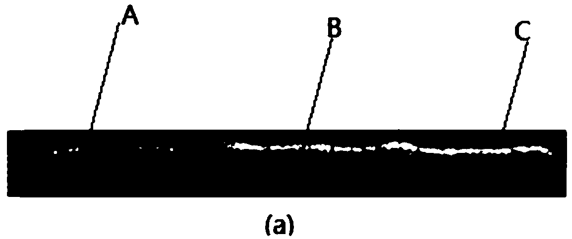
[0034] In this example, the schematic diagram of the additive molding object formed by laser additive manufacturing is shown in Figure 3(a). The molding layer is divided into three areas, namely A, B, and C areas. And the area when the defocus amount of area C is 0mm, and the area when the defocus amount is +3mm in area B. This situation is used to simulate the situation when the defocus amount changes during the production process.
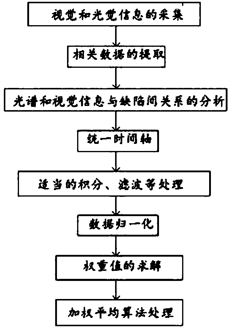
[0035] The flow chart of the online diagnosis method for defects in the specific laser additive manufacturing process is as follows: figure 2 As shown, the method includes the following steps:
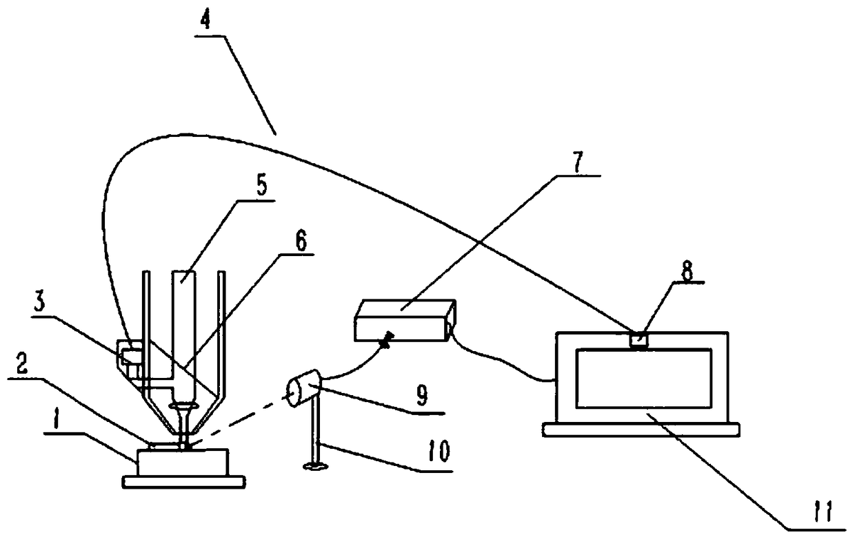
[0036] (1) Collection of spectral information: the optical fiber probe 9 collects the photoplasma spectral signal generated in the laser additive manufacturing process and sends it to the computer 11 through the optical fiber spectrometer 7, and according to the relative radiation intensity of the plasma of different wavelengths fluctuating with time si...
Embodiment 2
[0043] In this example, the schematic diagram of the additive molding object formed by laser additive manufacturing is shown in Figure 4(a). The molding layer is divided into three areas: D area, E area, and F area. The D area Areas F and F are the area when the laser power is 2000W, and area E is the area when the laser power is 1500W. This situation is used to simulate the situation when the laser power changes during the production process.
[0044] The flow chart of the online diagnosis method for defects in the specific laser additive manufacturing process is as follows: figure 2 As shown, the method includes the following steps:
[0045] (1) Collection of spectral information: the optical fiber probe 9 collects the photoplasma spectral signal generated in the laser additive manufacturing process and sends it to the computer 11 through the optical fiber spectrometer 7, and according to the relative radiation intensity of the plasma of different wavelengths fluctuating wi...
Embodiment 3
[0052] In this example, the schematic diagram of the additive molding object formed by laser additive manufacturing is shown in Figure 5(a). The molding layer is divided into three areas: H area, J area, and K area. The H area and K area are the area when there is protective gas, and J area is the area when there is no protective gas. This situation is used to simulate the situation when the protective gas changes during the production process.
[0053] The flow chart of the online diagnosis method for defects in the specific laser additive manufacturing process is as follows: figure 2 As shown, the method includes the following steps:
[0054] (1) Collection of spectral information: the optical fiber probe 9 collects the photoplasma spectral signal generated in the laser additive manufacturing process and sends it to the computer 11 through the optical fiber spectrometer 7, and according to the relative radiation intensity of the plasma of different wavelengths fluctuating w...
PUM
 Abstract
Description
Claims
Application Information
 - R&D
- Intellectual Property
- Life Sciences
- Materials
- Tech Scout
- Unparalleled Data Quality
- Higher Quality Content
- 60% Fewer Hallucinations
Browse by: Latest US Patents, China's latest patents, Technical Efficacy Thesaurus, Application Domain, Technology Topic, Popular Technical Reports.
© 2025 PatSnap. All rights reserved.Legal|Privacy policy|Modern Slavery Act Transparency Statement|Sitemap|About US| Contact US: help@patsnap.com