
Concrete mixer unit

A concrete and mixing technology, which is used in batching storage, batching weighing instruments, clay preparation devices, etc., can solve problems such as uneven thickness of raw materials, splashing of materials, and failure of material distribution, saving mixing time and processing. Efficiency improvement, wide range of use effects

Pending Publication Date: 2019-03-26
厦门市南昇机械设备有限公司
View PDF3 Cites 3 Cited by
  • Summary
  • Abstract
  • Description
  • Claims
  • Application Information

AI Technical Summary

Problems solved by technology

However, the raw material handler is shaped like a drum with a horizontal axis, which makes loading and unloading difficult
The huge rotatable roller fixed on the base has a roll, which undoubtedly increases the metal consumption of the unit, and the pressure is adjusted by the action of the pneumatic transmission cylinder and the pneumatic system to control the compaction of the roll. machine, undoubtedly making the structure of the unit more complicated
The disadvantage of the unit of similar schemes is also that the loading device on the conveyor belt in the shape of a multi-compartment carriage (box without bottom) cannot supply multi-layer raw materials of sufficient quality due to the following reasons
First, when the multi-grid carriage with raw materials is displaced along the metal sheet, the raw materials will easily accumulate on the rear wall due to uneven force, so the thickness of the raw materials in each grid is uneven during the movement of the carriage. of
Second, when the raw materials are unloaded from the grid to the conveyor belt, they are also uneven, and they are all in large pieces.
However, when feeding materials, such as cement, such feeding will cause splashing, and it will stick to some parts, which will cause the failure of material distribution
In summary, the main disadvantage of this machine is the lack of an effective raw material feeding device, which can create conditions for the rapid end of the raw material mixing phase and the rapid start of the raw material processing phase

Method used


Image

  • Concrete mixer unit
  • Concrete mixer unit
  • Concrete mixer unit

Examples


Embodiment Construction

[0015] Specific embodiments of the present invention will be described in detail below in conjunction with the accompanying drawings.

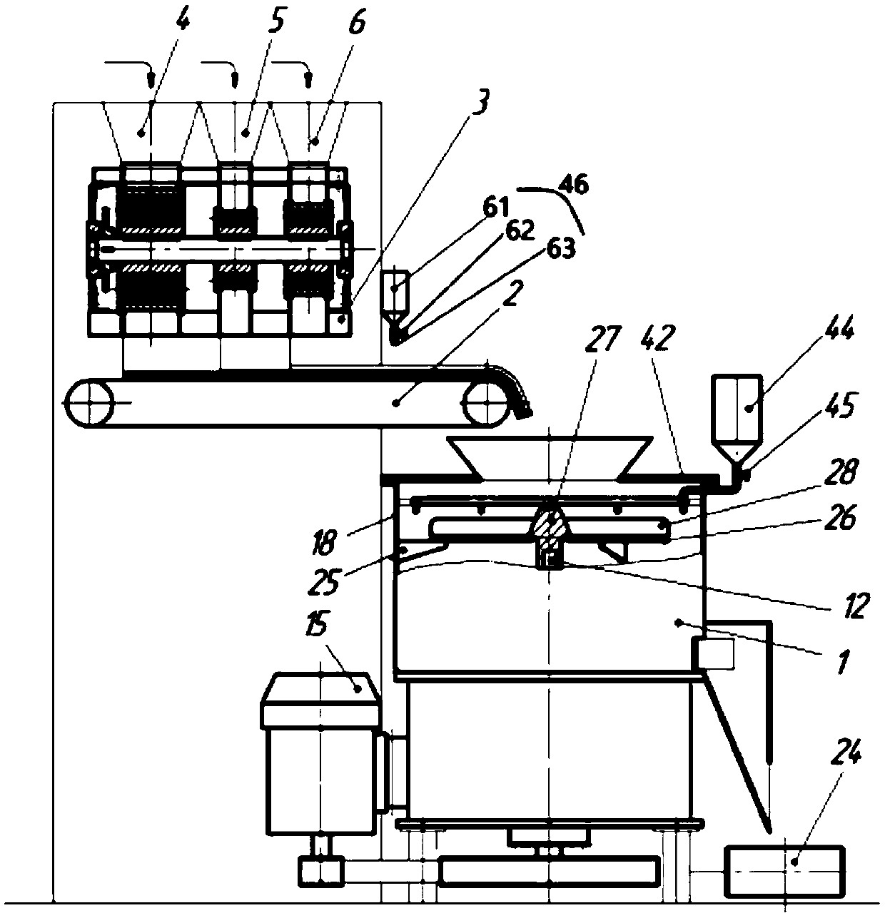
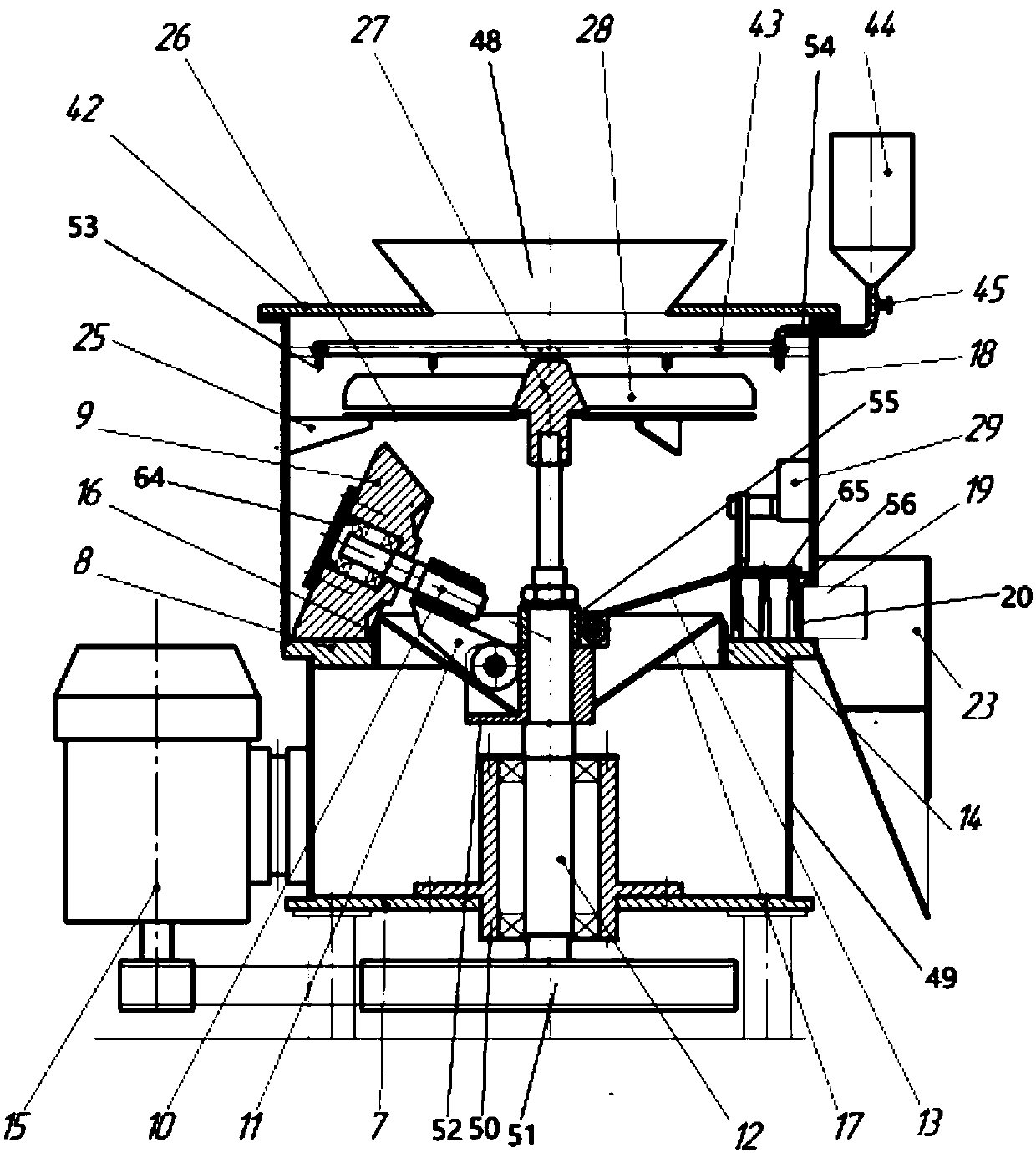
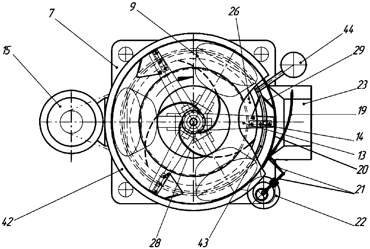
[0016] As shown in the figure, a concrete mixing unit is characterized in that it includes a raw material mixing processor 1, a belt feeder 2, a grid feeder 3, a hopper I4, a hopper II5, a hopper III6, and a conveyor belt I24; the hopper I4, hopper II5, and hopper III6 are respectively used to store various concrete raw materials; the partition feeder 3 is located above the belt feeder 2 and below the hopper I4, hopper II5, and hopper III6; the partition feeder 3 Parallel to the conveyor shaft 47 of the belt feeder 2; the raw material mixing processor 1 is located below the belt feeder 2; the feed inlet of the raw material mixing processor 1 is connected to the belt feeder The discharge port 48; the conveyor belt I24 is located below the side of the raw material mixing processor 1 for receiving and delivering the processed raw materials.

[0...


PUM


Abstract

The invention provides a concrete mixer unit. The concrete mixer unit comprises a raw material stirring processor, a belt feeder, a separation feeder, a hopper I, a hopper II, a hopper III and a conveyor belt I. The hopper I, the hopper II and the hopper III are used for storing various types of concrete materials. The separation feeder is located above the belt feeder and below the hopper I, thehopper II and the hopper III. The separation feeder is parallel to a conveyor belt shaft of the belt feeder. The raw material stirring processor is located below the belt feeder. A feed port of the raw material stirring processor is connected with a discharge port of the belt feeder. The conveyor belt I is located below the raw material stirring processor and used for receiving and conveying processed raw materials. A feeding device of the separation feeder of the concrete mixer unit is provided with a moving part. The volume of a feeding unit of the feeding device can be effectively adjustedby adjusting the position of the moving part, and then quantitative feeding is realized. The concrete mixer unit is wider in application range and more convenient to use.

Description

technical field [0001] The invention relates to building material processing equipment, in particular to a concrete mixing unit. Background technique [0002] There are many concrete mixing treatment equipments on the market at present, they have solved some problems in the production process, but still have many deficiencies, such as publication number is that CN206027478U agitator is the raw material treatment machine that has the fixed annular spacer that is made , the unit has a planetary gear-shaped mixer and a roller with a fixed cup plate. This unit operates at a low speed, and the pressure intensity when the roller rolls the raw material layer cannot be guaranteed, nor can it be adjusted. The processing machine with the publication number CN201820360139.0, this fast mixing unit can ensure that the raw material components are mixed quickly and fully. This is not only because the feeding is not dispersed, but in the form of multi-layer raw material blocks, but also be...

Claims


Application Information

Patent Timeline
IPC IPC(8): B28C5/16B28C7/06B28C7/00B28C7/12B28C7/02B28C7/04
CPCB28C5/0806B28C5/16B28C7/0053B28C7/02B28C7/044B28C7/06B28C7/067B28C7/12
Inventor 刘山萨夫琴科·亚历山大·格里戈里耶维奇费多罗夫·格奥尔基·德米耶里特维奇科勒克夫·罗曼·彼得罗维奇巴克伊.威亚切斯拉夫.亚历山大罗维奇康斯坦丁·阿米尔科夫
Owner 厦门市南昇机械设备有限公司
Learn More