Drying system for plastic foam particle film

A drying system and plastic foam technology, which is applied in the field of plastic foam particle-coated drying system, can solve the problems of unguaranteed production quality, inability to collude with hot spots, and large heat energy consumption, etc., to achieve particle quality assurance and drying effect Good, the effect of reducing energy consumption

Pending Publication Date: 2019-03-26
菲尔普(青岛)新材料有限公司
View PDF12 Cites 2 Cited by
  • Summary
  • Abstract
  • Description
  • Claims
  • Application Information

AI Technical Summary

Problems solved by technology

[0005] In the above-mentioned patent, the spiral stirring device and the air supply device can prevent the sticking of the flame-retardant granular material, and the forward stirring fin plate can re-stir the granular material, and at the same time send the granular material out of the dryer. Although it can reduce energy consumption, its There is only an air supply device, and no air circulation channel can be formed in the stirring drying drum, and the drying speed is slow, so the particles wrapped with a layer of inorganic flame retardants are easy to stick together and settle to the bottom of the drum, even if adjusted The wind power of the high air supply device also has the situation of subsidence, the productivity is low and the bottom of the cylinder is not easy to clean, it is time-consuming and laborious, the energy consumption is large, and the production capacity is low
Secondly, there are particles that have not been dried and are discharged from the dryer by advancing the stirring and drying sheet, and adhesion between the undried particles will occur, which will affect the processing and production of subsequent particles, and the production quality cannot be guaranteed. , the heat exchanger and the drying oven are connected in parallel, and the hot spots cannot be connected together, and the heat energy consumption is large, resulting in large energy consumption

Method used


Image

  • Drying system for plastic foam particle film
  • Drying system for plastic foam particle film
  • Drying system for plastic foam particle film

Examples


Embodiment Construction

[0019] The present invention will be described in further detail below in conjunction with the accompanying drawings and specific embodiments.

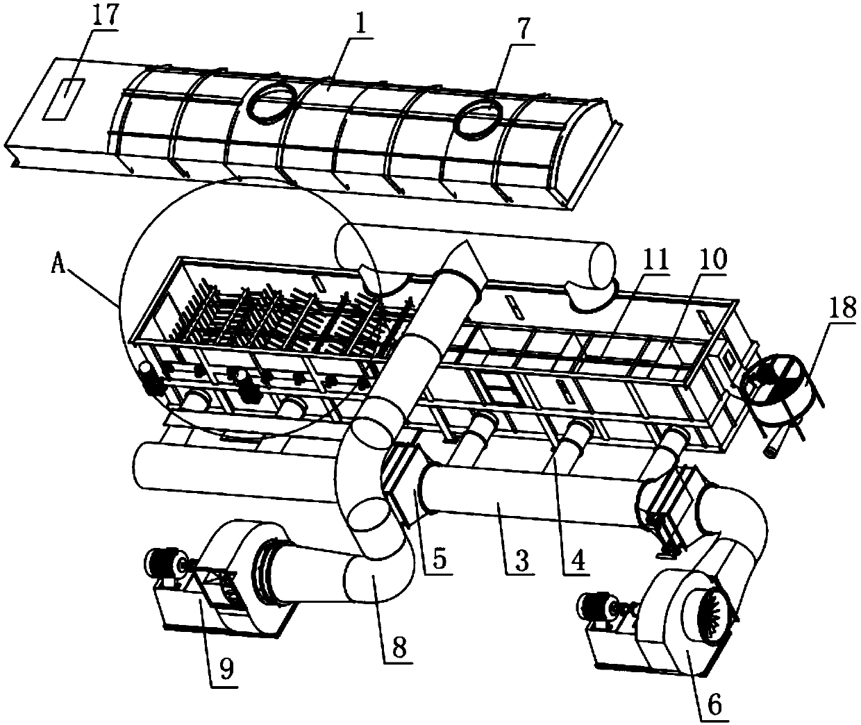
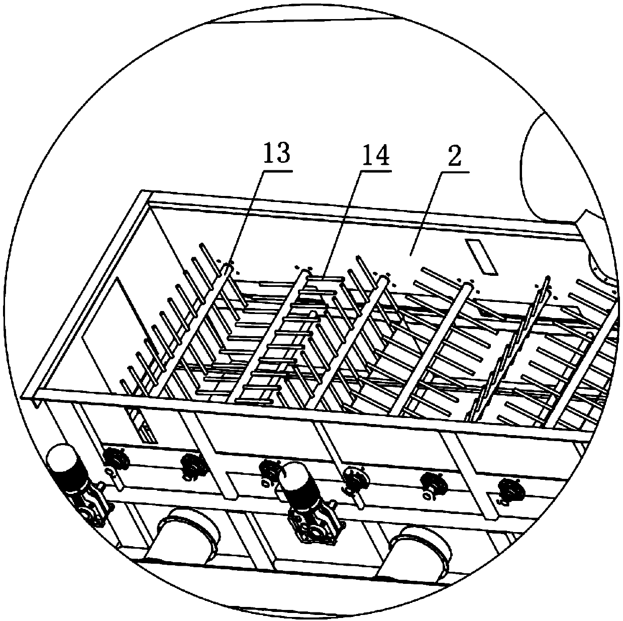
[0020] like figure 1 , 2 , Shown in 3, a kind of drying system that is used for plastic foam granule coating, comprises the drying cavity 2 that forms a sealed cavity with top cover 1 and top cover and is provided with in drying cavity 2 The device also includes an air inlet device connected to the lower part of one side of the drying chamber 2 to keep the particles in the drying chamber in a suspended state, and an air exhaust device that forms an air circulation with the air inlet device for comprehensive and rapid drying.

[0021] The air inlet device comprises a plurality of air inlet pipes 4 arranged in series through the air blast duct 3, and the air blast pipe 3 is provided with a radiator 5 for providing heat to assist drying for the drying cavity, and the series arrangement of the air inlet pipe 4 can be Realize heat energy...


PUM


Abstract

The invention relates to the technical field of foam particle processing machinery, in particular to a drying system for a plastic foam particle film. The drying system comprises a drying cavity and adrying device, wherein the drying cavity is provided with a top cover, a sealed cavity is formed by the top cover and the drying cavity, and the drying device is arranged in the drying cavity. The drying system further comprises an air inlet device and an air outlet device, wherein the air inlet device is connected with the lower part of one side face of the drying cavity and is used for enablingparticles in the drying cavity to be in a suspended state, air circulation is formed by the air inlet device and the air outlet device to carry out comprehensive and rapid drying, and the air inlet device comprises a plurality of air inlet pipes which are connected through a blast pipeline in series. According to the drying system, the multiple air inlet pipes in the air inlet device are connected through the blast pipeline in series to achieve circulation of heat energy, the energy consumption is reduced, air circulation in the drying cavity is achieved through an induced draft fan and an air blower, the particles are dried by 360 degrees without dead corners, air with moisture in the drying cavity is discharged, the particle speed is high, the particles are not prone to adhering, the drying effect is good, the energy consumption is low, and the working efficiency is high.

Description

technical field [0001] The invention relates to the technical field of foam particle processing machinery, in particular to a drying system for plastic foam particle coating. Background technique [0002] Plastic foam is a kind of chemical material, its full name is expanded polystyrene foam (EPS for short), because of its light weight, firmness, shock absorption, low moisture absorption, easy molding, good water resistance, heat insulation, and low price, etc. , is widely used in packaging, heat preservation, waterproof, heat insulation, shock absorption and other fields, and is one of the most widely used plastics in the world today. [0003] Because EPS has good light weight and good thermal insulation effect, it is now widely used in the building thermal insulation material industry. However, in recent years, due to the non-flammability of building insulation materials in various places, major fires have occurred continuously, causing huge losses in manpower and mater...

Claims


Application Information

Patent Timeline
Patent Type & Authority Applications(China)
IPC IPC(8): B29B13/06
CPCB29B13/065
Inventor 刘庆杨徐嵩肖天宇彭国生
Owner 菲尔普(青岛)新材料有限公司
Why Eureka
Try Eureka