High-bearing and low-friction suspension type antenna unloading device

An unloading device and low-friction technology, which is applied in the simulation device of space navigation conditions, transportation and packaging, space navigation equipment, etc., can solve the problems of narrow application area, low carrying capacity, and the inability to realize the adaptive adjustment of the center of mass of the antenna, etc., to achieve The effect of reducing the complexity of the pipeline and reducing the difficulty of processing

Active Publication Date: 2019-03-26
SHANGHAI AEROSPACE SYST ENG INST
View PDF6 Cites 10 Cited by
  • Summary
  • Abstract
  • Description
  • Claims
  • Application Information

AI Technical Summary

Problems solved by technology

[0006] 2. This method has a narrow scope of application and is only suitable for a type of antenna with a process support interface reserved at the bottom of the radar antenna
[0008] 1. The carrying capacity of this method is low, and it is only suitable for satellite loads with a weight of no more than 50kg, such as solar arrays;
[0009] 2. The air-floating long guide rail of this method is an integral configuration. With the increase of the radar antenna array, the long-span unloading movement range makes the processing and assembly of the long guide rail difficult;
[0012] 5. This method is a single suspension point suspension, which cannot realize the pose adjustment during the antenna assembly process;
[0013] 6. The action line of the unloading force in this method is fixed relative to the antenna, which cannot realize the adaptive adjustment of the hanging force to the centroid position of the antenna, which affects the accuracy of the deployment test

Method used


Image

  • High-bearing and low-friction suspension type antenna unloading device
  • High-bearing and low-friction suspension type antenna unloading device
  • High-bearing and low-friction suspension type antenna unloading device

Examples


Embodiment Construction

[0063]The following will clearly and completely describe the technical solutions in the embodiments of the present invention with reference to the accompanying drawings in the embodiments of the present invention. Obviously, the described embodiments are only some, not all, embodiments of the present invention. Based on the embodiments of the present invention, all other embodiments obtained by persons of ordinary skill in the art without making creative efforts belong to the protection scope of the present invention.

[0064] The terms "first", "second", "third", "fourth", etc. (if any) in the description and claims of the present invention and the above drawings are used to distinguish similar objects and not necessarily Describe a specific order or sequence. It is to be understood that the data so used are interchangeable under appropriate circumstances such that the embodiments of the invention described herein can be practiced in sequences other than those illustrated or ...


PUM


Abstract

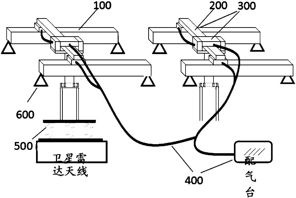
The invention provides a high-bearing and low-friction suspension type antenna unloading device. The high-bearing and low-friction suspension type antenna unloading device comprises long air flotationguide rails, short air flotation guide rails, an air supply and distribution system, a double-suspension-bar suspension assembly and a bearing truss. The long air flotation guide rails are arranged on the bearing truss and driven by the air supply and distribution system to move relative to the bearing truss. The two ends of each short air flotation guide rail are arranged on the two corresponding long air flotation guide rails correspondingly, and the short air flotation guide rails are driven by the air supply and distribution system to move relative to the long air flotation guide rails. The double-suspension-bar suspension assembly is connected with the two ends of each short air flotation guide rail in a sliding mode, driven by the air supply and distribution system to move relativeto the short air flotation guide rails and used for achieving suspension of load antennas. By the adoption of the high-bearing and low-friction suspension type antenna unloading device, the long air flotation guide rails and the short air flotation guide rails are driven by the air supply and distribution system, so that linear movement of the double-suspension-bar suspension assembly in the orthogonal direction of the long guide rails is achieved. The double-suspension-bar suspension assembly is connected with satellite radar antennas, so that gravity unloading of the satellite radar antennasis achieved.

Description

technical field [0001] The invention relates to the technical field of satellite AIT, in particular to a high-load-bearing and low-friction suspension antenna unloading device applied to zero-gravity simulation in the installation and deployment of space-borne planar antennas and deployment tests. Background technique [0002] The planar array radar antenna is an important payload in the satellite field. After the satellite is put into orbit, the above-mentioned antenna needs to change from the folded state to the unfolded locked state in the zero-gravity environment of the orbit according to the procedure. These deployments are the key to the success of the satellite mission. Therefore, the ground In the adjustment and deployment tests, a large number of experimental verifications are required for these deployment actions. [0003] Since the kinematic and mechanical properties of all movable joints of the planar array radar antenna are designed according to the on-orbit zer...

Claims


Application Information

Patent Timeline
Patent Type & Authority Applications(China)
IPC IPC(8): B64G7/00
CPCB64G7/00
Inventor 肖杰王浩王中王刘哲臣程庆清齐德强陈飞飞瞿佳蔚黄利强徐庆李舒扬
Owner SHANGHAI AEROSPACE SYST ENG INST
Why Eureka
Try Eureka