Eureka AIR delivers breakthrough ideas for toughest innovation challenges, trusted by R&D personnel around the world.

Diesel engine particulate filter regeneration system and methods

A technology of engine system and diesel engine, which is applied in the direction of engine components, combustion engine, engine control, etc., can solve problems such as exhaust restriction, and achieve the effects of improved control, improved torque control and engine emissions

Pending Publication Date: 2019-03-26
FORD GLOBAL TECH LLC
View PDF0 Cites 2 Cited by
  • Summary
  • Abstract
  • Description
  • Claims
  • Application Information

AI Technical Summary

Problems solved by technology

Over time, the particulate filter can become filled with soot causing it to provide a more significant restriction on the exhaust

Method used


Image

  • Diesel engine particulate filter regeneration system and methods
  • Diesel engine particulate filter regeneration system and methods
  • Diesel engine particulate filter regeneration system and methods

Examples


Embodiment Construction

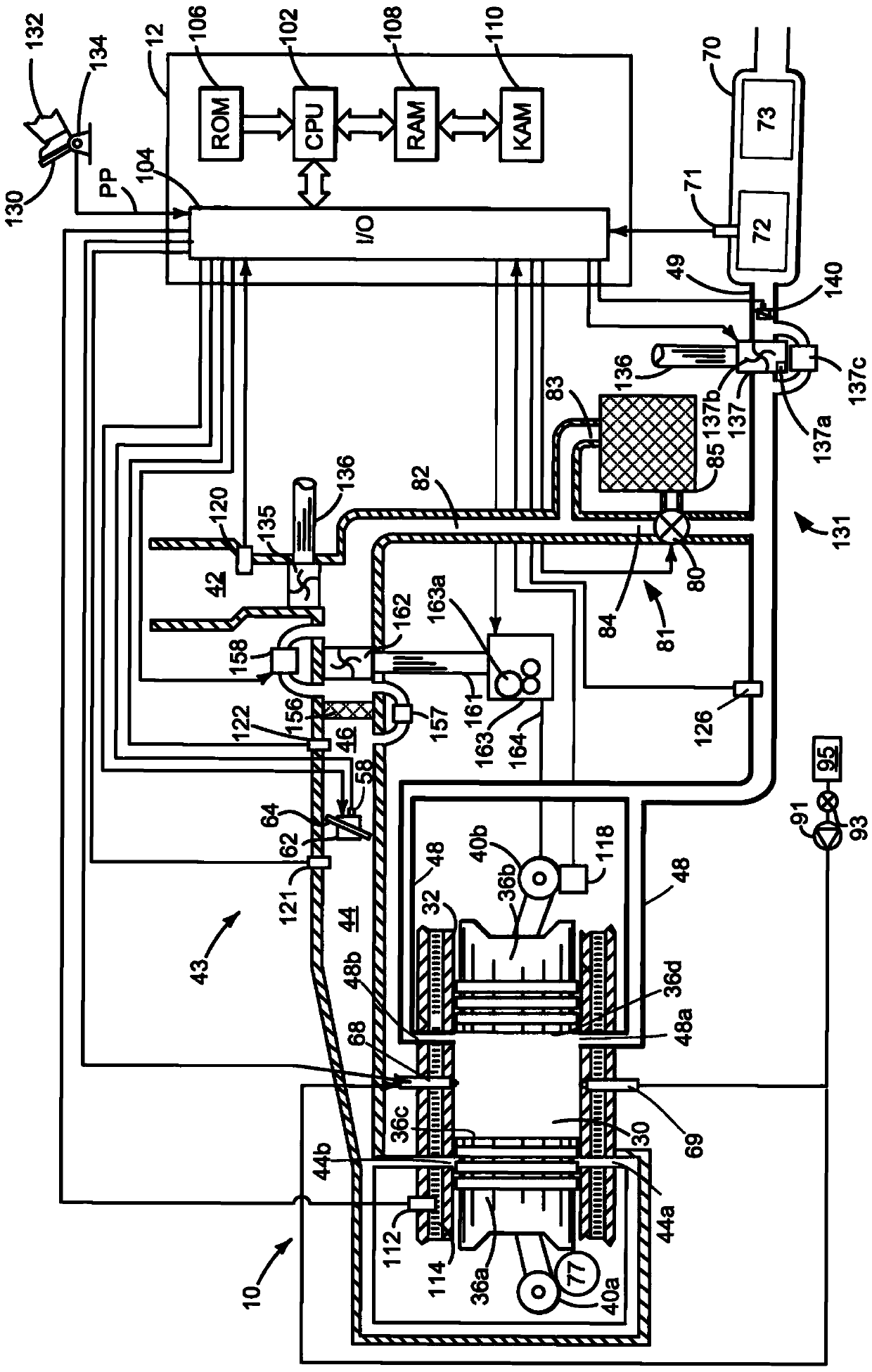
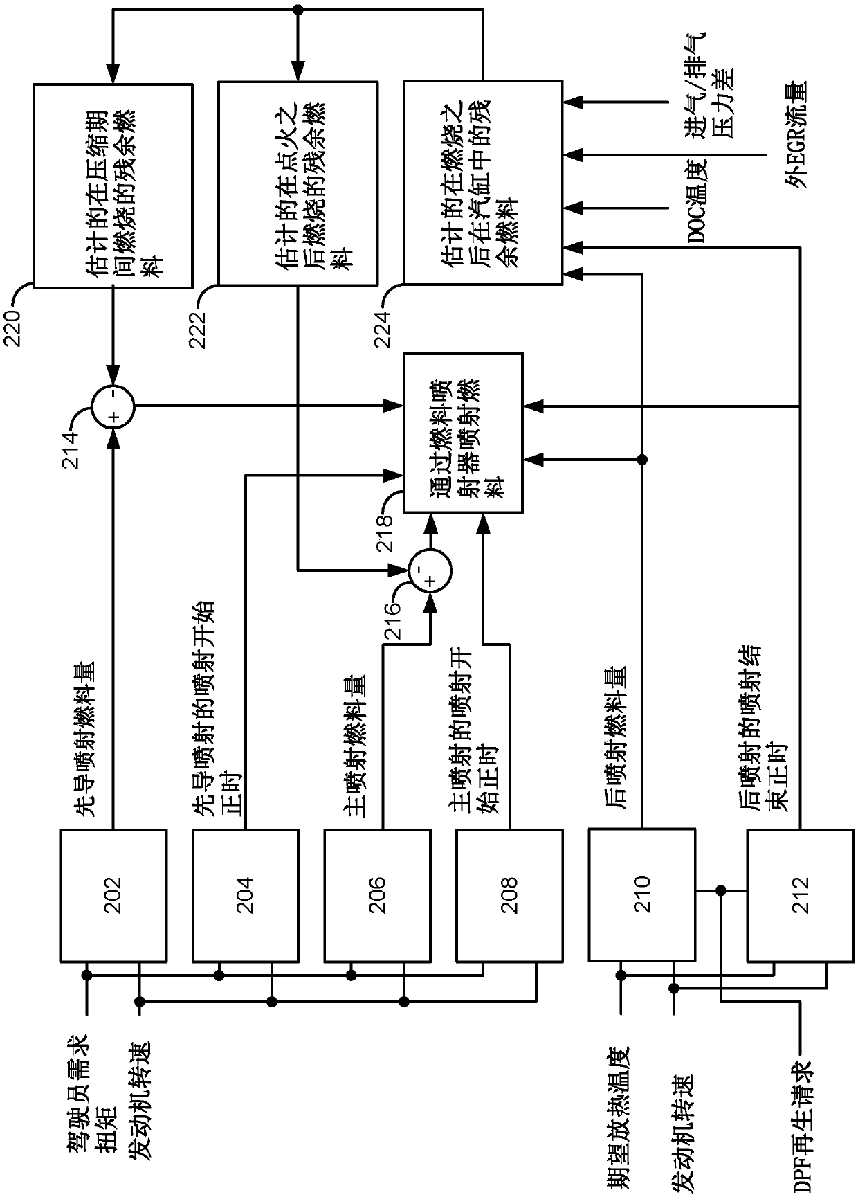
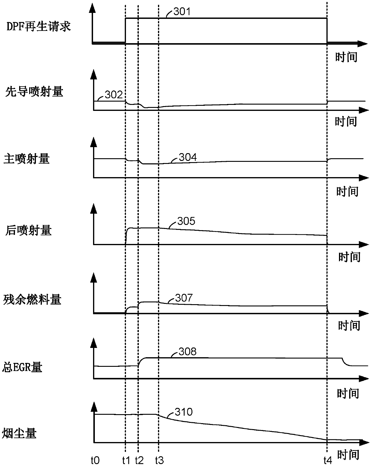
[0012] The present invention relates to controlling the fuel supplied to a diesel engine. figure 1 An example of a supercharged two-stroke diesel engine is shown, but the methods described herein are equally applicable to four-stroke diesel engines. and, figure 1 The diesel engine in is an opposed-piston engine, but the methods described herein can also be applied to two-stroke engines that contain a single piston per engine cylinder. figure 2 A block diagram showing the manner in which fuel injection is adjusted. The fuel injection sequence for a diesel engine is in image 3 is shown in . A method for supplying fuel to a diesel engine in Figure 4 is shown in .

[0013] refer to figure 1 , containing multiple cylinders (one of which is in figure 1 An opposed-piston internal combustion engine 10 shown in ) is controlled by an electronic engine controller 12 . The controller 12 receives from figure 1 signals from various sensors and utilizes based on the received sign...


PUM


Abstract

The invention relates to a diesel engine particulate filter regeneration system and methods. Methods and systems for estimating an amount of residual or retained fuel that remains in a cylinder from afirst cycle of the cylinder to a second cycle of the cylinder are described. In one example, the amount of residual fuel is estimated in response to a temperature of an oxidation catalyst. The retained fuel amount may then be the basis for adjusting fuel injection amounts during the second cycle of the cylinder.

Description

technical field [0001] The present invention relates to diesel engine particulate filter regeneration systems and methods. Background technique [0002] Two-stroke diesel engines and four-stroke diesel engines that include variable valve timing may operate with relatively large amounts of residual exhaust gas left in the engine cylinders from previous combustion events in the engine cylinders. These same engines may include particulate filters in their exhaust systems to capture carbonaceous soot that may be produced as a byproduct of combustion. Over time, the particulate filter can become saturated with soot causing it to provide a more significant restriction on the exhaust. The particulate filter may be regenerated by increasing exhaust temperature and supplying an oxygen-rich exhaust mixture to the particulate filter to burn soot left in the particulate filter, thereby regenerating the microfiltration filter. Exhaust temperature may be increased by injecting post fuel...

Claims


Application Information

Patent Timeline
Patent Type & Authority Applications(China)
IPC IPC(8): F02D41/40F02D41/02
CPCF02D41/029F02D41/402F02D41/403F02D41/405F02D2200/0616F02D2200/0802F01N3/021F01N3/103F01N9/002F01N2430/06F01N2900/08F01N2900/1602F02B75/282F02D41/3094F02D2200/0406F02M26/04Y02T10/40F01N3/025F01N11/002F01N2900/1406
Inventor E·M·库尔茨E·J·卡斯塔尼斯
Owner FORD GLOBAL TECH LLC
Why Eureka
Eureka Blog
Learn More