High-temperature air source heat pump suitable for ultra-low-temperature environment

A high-temperature air and source heat pump technology, which is applied to fluid heaters, lighting and heating equipment, and compressors with cascade work, etc., can solve the problem of insufficient heat supply, unstable operation of air source heat pumps, and changes in thermal properties, etc. problems, to achieve the effect of improving heating capacity and energy efficiency, solving insufficient heat supply, and reducing exhaust temperature

Pending Publication Date: 2019-03-26
春意环境科技有限公司
View PDF0 Cites 7 Cited by
  • Summary
  • Abstract
  • Description
  • Claims
  • Application Information

AI Technical Summary

Problems solved by technology

[0006] The purpose of the present invention is to overcome the above shortcomings, thereby providing a high-temperature air source heat pump suitable for ultra-low temperature environments, which can avoid the problem of thermophysical property changes of refrigerants at high and low temperatures, and effectively improve the heating capacity and energy efficiency of air source heat pumps , reduce the exhaust temperature, solve the problem of insufficient heat supply during the first stage of compression, and ensure that the overall heating capacity is sufficient; in addition, the two operating modes of the low temperature difference and high temperature difference of the present invention solve the problem that the air source heat pump suffers from large changes in the ambient temperature The problem of unstable operation during the process improves the environmental adaptability of the air source heat pump

Method used


Image

  • High-temperature air source heat pump suitable for ultra-low-temperature environment
  • High-temperature air source heat pump suitable for ultra-low-temperature environment

Examples


Embodiment Construction

[0022] Below the present invention will be further described in conjunction with the embodiment in the accompanying drawing:

[0023] The following describes several preferred embodiments of the present invention with reference to the accompanying drawings, so as to make the technical content clearer and easier to understand. The present invention can be embodied in many different forms of embodiments, and the protection scope of the present invention is not limited to the embodiments mentioned herein. The size and thickness of each component shown in the drawings are arbitrarily shown, and the present invention does not limit the size and thickness of each component.

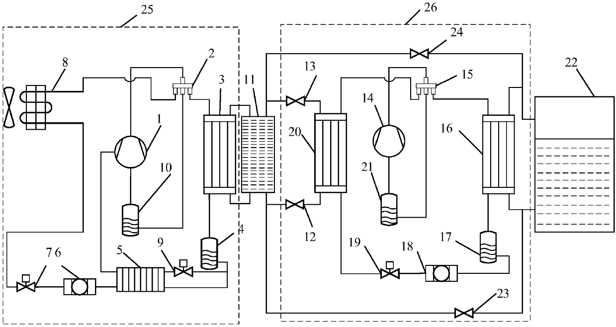
[0024] Such as figure 1 as shown, figure 1It is a structural schematic diagram of a preferred embodiment of the present invention. Wherein, the air source heat pump is composed of a first air source system 25, a second air source system 26, an intermediate heat exchanger 11 and a water tank 22, and the first...


PUM


Abstract

The invention relates to a high-temperature air source heat pump suitable for ultra-low-temperature environment and belongs to the technical field of ultra-low-temperature air source heat pumps. The high-temperature air source heat pump suitable for the ultra-low-temperature environment comprises a first air source system, a second air source system, an intermediate heat exchanger and a water tank. The first air source system and the second air source system are connected with the intermediate heat exchanger through pipelines, and the water tank is connected with the second air source system and the intermediate heat exchanger through pipelines. According to the high-temperature air source heat pump, by the adoption of a two-stage coupling system, the temperature range experienced by a refrigerant in the cycle is separated, so that the problem of the thermophysical property changes of the refrigerant at high temperature and low temperature is avoided; the first air source system adoptsair supplement to increase enthalpy, so that the heat production and energy efficiency of the air source heat pump are effectively improved, the exhaust temperature is lowered, the problem of insufficient heat supply during the first-stage compression is solved, sufficient overall heat production is ensured, and the environmental adaptability of the air source heat pump is improved.

Description

technical field [0001] The invention relates to a high-temperature air source heat pump suitable for ultra-low temperature environments, and belongs to the technical field of ultra-low temperature air source heat pumps. Background technique [0002] The water supply temperature for building heating is generally around 80°C. Due to the high temperature of the water supply, the heating process is mainly realized through urban central heating or district boilers. The application of air source heat pumps in conventional building central heating systems is still very limited. A heat pump is a device that transfers thermal energy from a low-temperature heat source to a high-temperature heat source at the cost of consuming high-quality energy. The air source heat pump can extract the low-temperature heat energy in the air, and has the characteristics of high energy efficiency, simple structure, no pollution, and easy installation. Due to these advantages of the air source heat p...

Claims


Application Information

Patent Timeline
Patent Type & Authority Applications(China)
IPC IPC(8): F25B7/00F24H4/04
CPCF25B7/00F24H4/04
Inventor 刘兴非冉小鹏翟晓强刘彦杰陈建新骆琼
Owner 春意环境科技有限公司
Why Eureka
Try Eureka