Check patentability & draft patents in minutes with Patsnap Eureka AI!

Laser projection system

A technology of laser projection and laser, which is applied in the field of projection, can solve the problems of increasing the cost of the projector, difficulty in heat dissipation of the projector, and difficulty in heat dissipation, so as to improve the utilization rate of light energy, reduce the contrast of speckle, and promote the effect of system volume

Active Publication Date: 2019-03-26
HEFEI INSTITUTES OF PHYSICAL SCIENCE - CHINESE ACAD OF SCI
View PDF9 Cites 4 Cited by
  • Summary
  • Abstract
  • Description
  • Claims
  • Application Information

AI Technical Summary

Problems solved by technology

Although no color wheel is used, this solution has the following defects: (1) due to the coherence of the laser, speckle will appear in the projected display image, which affects the display effect; (2) the laser needs to pass through three groups of dichroic On each dichroic mirror, the light energy will be lost, the cost of the dichroic mirror is relatively high, and the angle of incidence of the incident light is strictly required. In the process of production or transportation, it cannot As a result, the angle at which the incident light enters the dichroic mirror changes, and the overall installation is more difficult; (3) The lens matrix is ​​closely arranged with gradient index lenses with the same geometric parameters, optical characteristics and processing accuracy
However, this solution has the following defects: (1) the illuminance of a single LD projector is low, increasing the power of a single LD will cause problems such as difficult heat dissipation of the projector; (2) silicon-based liquid crystals are expensive, which increases the the cost of
[0005] Existing laser projection system solutions cannot effectively suppress laser speckle, and at the same time, there are problems such as low utilization rate of light energy, complex structure, many components, large volume, high cost, and difficulty in heat dissipation

Method used


Image

  • Laser projection system
  • Laser projection system
  • Laser projection system

Examples


Embodiment 1

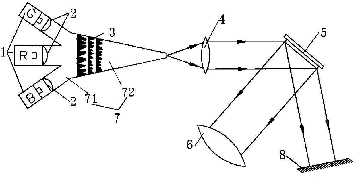
[0043] Such as figure 1 As shown, a laser projection system includes

[0044] Laser light source 1, which emits light of different colors and is used to synthesize white light;

[0045] The first shaping lens 2 converts the light emitted by the laser light source 1 into the incident light required for Mie scattering by the scattering sheet 3;

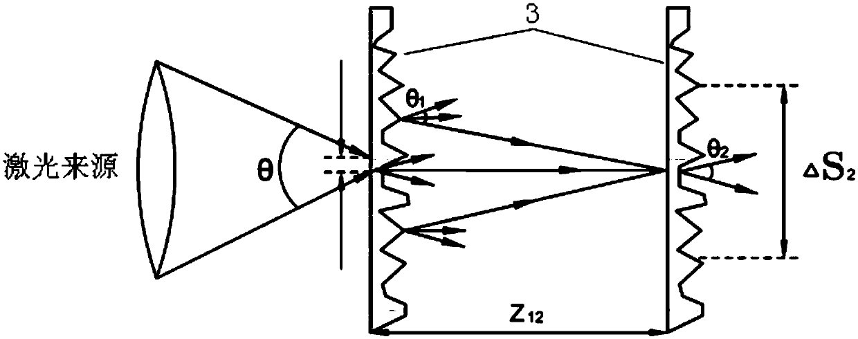
[0046] The scattering sheet 3 is used to reduce the coherence of the laser light source 1;

[0047]The second shaping lens 4, the second shaping lens 4 is a rectangular lens, and the distance from the opening end of the light guide pipe 7 is one times the focal length, and is used to uniformly shape the light emitted by the scattering sheet 3 into parallel light;

[0048] The digital micromirror element 5 controls whether the light is reflected onto the projection lens 6;

[0049] The projection lens 6 is used to display the projection effect;

[0050] The system also includes a light pipe 7 absorber 8, one end of the light pipe 7 i...

Embodiment 2

[0080] The difference from Embodiment 1 is that the length of the light pipe 7 is 6 cm, or 7 cm.

Embodiment 3

[0082] The difference from Embodiment 1 is that the number of scattering sheets 3 is 4, or 5.


PUM

PropertyMeasurementUnit
Lengthaaaaaaaaaa
Lengthaaaaaaaaaa

Abstract

The invention discloses a laser projection system, which comprises a laser source emitting light of different colors and used for synthesizing white light; a first shaping lens converting the light emitted by the laser source into incident light required by a scattering sheet for Mie scattering; the scattering sheet for reducing the coherence of the laser source; a second shaping lens for uniformly shaping the light emitted by the scattering sheet into parallel light; a digital micromirror element for controlling whether to reflect the light to a projection lens; and the projection lens for displaying a projection effect, wherein the laser source, the first shaping lens, the scattering sheet, the second shaping lens, the digital micromirror element, and the projection lens are arranged successively according to an optical path. The system further includes a light guide tube having an open end. The laser source, the first shaping lens, and the scattering sheet are all disposed in the light guide tube. The open end of the light guide tube is located between the scattering sheet and the second shaping lens and is configured to form the light emitted by the scattering sheet into a point source. The laser projection system has a small number of components, the system volume is reduced, the system cost is reduced, and the light energy utilization rate of the system is improved.

Description

technical field [0001] The invention relates to the field of projection technology, in particular to a laser projection system. Background technique [0002] In recent years, as people have higher and higher requirements for the image quality projected by projectors, traditional light sources such as halogen lamps, xenon lamps, and mercury lamps can no longer meet people's needs. In the selection of projector light sources, people have paid attention to Focused on the field of laser lighting. Compared with traditional light sources, laser projectors have the advantages of wide color gamut, high contrast, and high brightness, and are generally expected to become the mainstream lighting source for next-generation digital projection display systems. [0003] In the journal "Laser and Optoelectronics Progress" published in October 2011, Rui Dawei and others published "Design of Illumination Optical Path for Laser Projector Based on Gradient Index Lens", which disclosed a The l...

Claims


Application Information

Patent Timeline
IPC IPC(8): G03B21/20
CPCG03B21/2033
Inventor 刘东钱立勇朱向冰刘阳张颖
Owner HEFEI INSTITUTES OF PHYSICAL SCIENCE - CHINESE ACAD OF SCI
Features
  • R&D
  • Intellectual Property
  • Life Sciences
  • Materials
  • Tech Scout
  • Unparalleled Data Quality
  • Higher Quality Content
  • 60% Fewer Hallucinations
Learn More