
Cathode inward rotating type pacemaker implanting test line

A test line, internal rotation technology, applied in the field of medical devices, can solve the problems of test line winding and knotting, patient pain, screw-in end screwed in and need to turn back, etc., to achieve the effect of simple structure and convenient use

Pending Publication Date: 2019-03-29
NINGBO NO 2 HOSPITAL
View PDF0 Cites 3 Cited by
  • Summary
  • Abstract
  • Description
  • Claims
  • Application Information

AI Technical Summary

Problems solved by technology

In the current technology, the cathode of the electrode end of the 3830 pacing electrode wire is fixed by the alligator clip and connected to the monitor through the cathode test line, and the patient's skin is used as the anode, which is fixed by the alligator clip and connected to the monitor and the pacing program control through the anode test line During the monitoring process, according to different situations, you can also choose to clip the alligator clip on the anode ring, and connect it to the monitor and pacemaker program controller through the anode ring test line to obtain more and more accurate data; When the operator rotates the outer skin of the 3830 pacing electrode lead, the end of the test line fixed by the alligator clip cannot rotate synchronously, causing the test line at this position to be entangled and knotted. It is impossible to continuously monitor the changes of ECG and electrode impedance in real time. However, the ECG change itself is an important basis for guiding whether the screw-in end is screwed in. state, or loosen the alligator clip after screwing in a stroke, untie the knotted part of the test line, and then clamp the alligator clip to monitor whether it is screwed in place. Such repeated operations will bring inconvenience to the operator, and often Due to untimely monitoring, the screw-in end has to be screwed in and needs to be turned back, which brings pain to the patient

Method used


Image

  • Cathode inward rotating type pacemaker implanting test line
  • Cathode inward rotating type pacemaker implanting test line
  • Cathode inward rotating type pacemaker implanting test line

Examples


Embodiment Construction

[0020] A cathode internal rotation pacemaker implant test line of the present invention will be described in detail below with reference to the accompanying drawings.

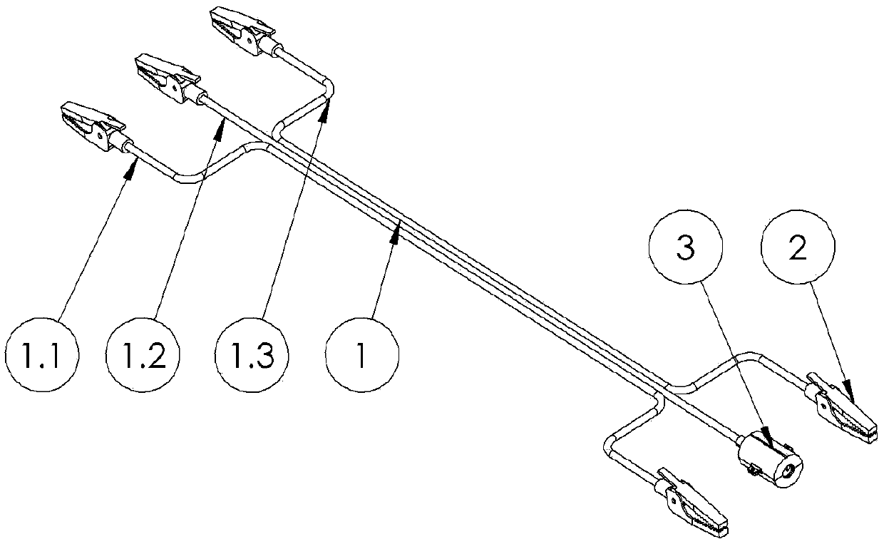
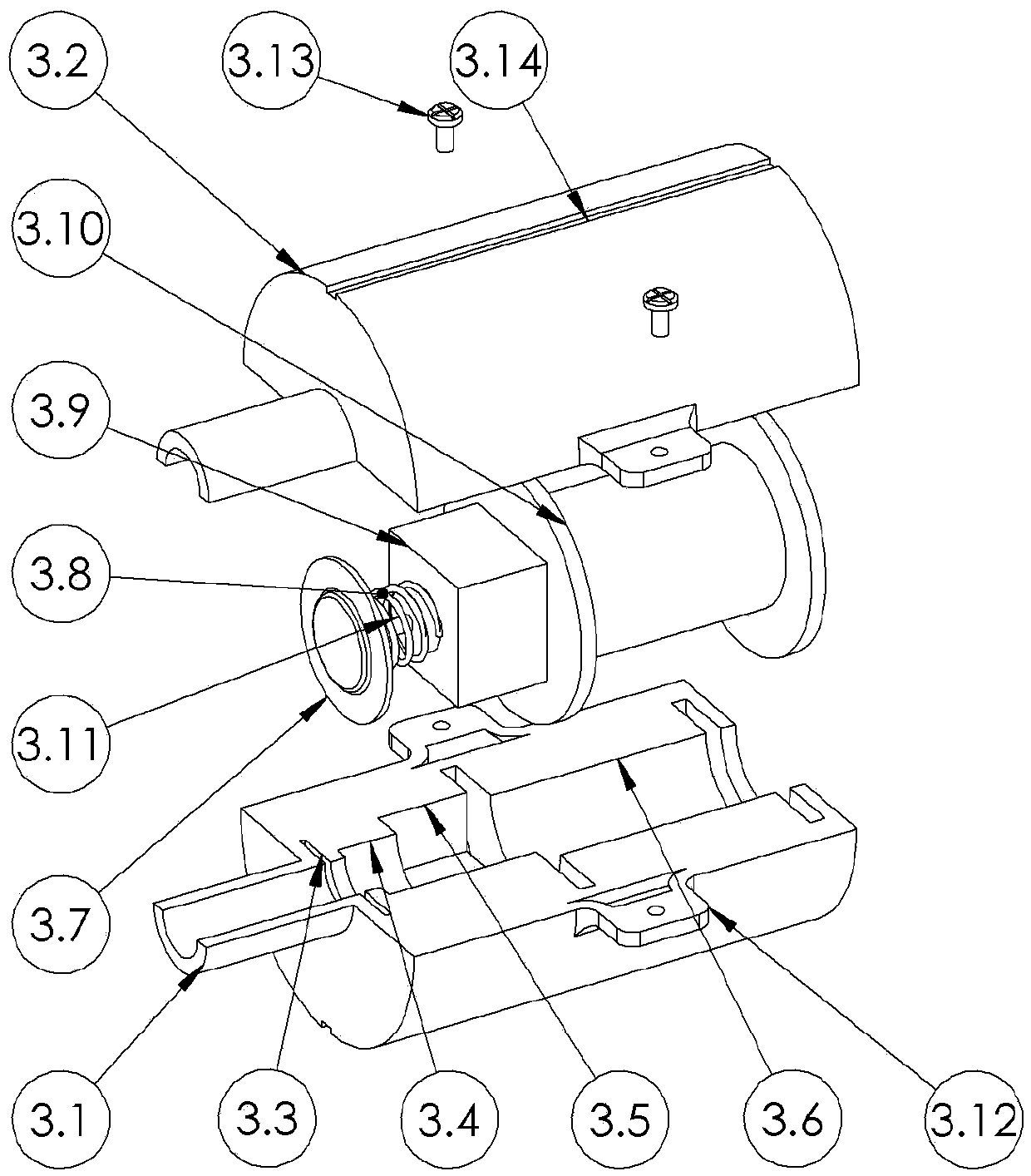
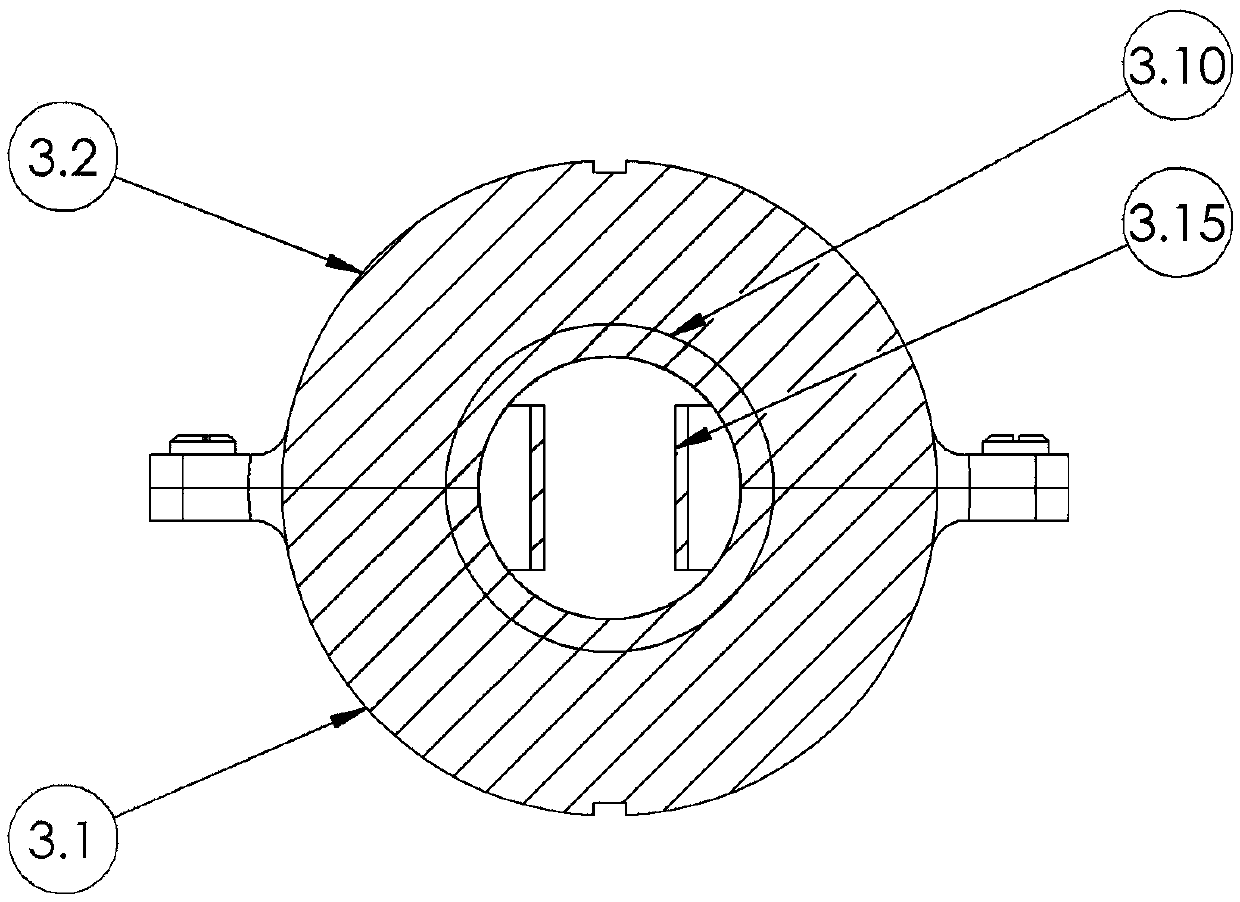
[0021] like figure 1 , figure 2 , image 3 As shown, a cathode internal rotation pacemaker implant test line includes a test line 1, and the test line 1 includes an anode ring test line 1.1, a cathode test line 1.2, a subcutaneous anode test line 1.3; an anode ring test line 1.1 and a subcutaneous Both ends of the anode test line 1.3 are fixedly connected with the crocodile clip 2; one end of the cathode test line 1.2 is fixedly connected with the crocodile clip 2, and the other end is fixedly connected with the rotatable cathode clip 3; the rotatable cathode clip 3 includes the lower shell 3.1 and the upper The shell 3.2; the lower shell 3.1 and the upper shell 3.2 are provided with the first placement slot 3.3, the second placement slot 3.4, the third placement slot 3.5, the fourth placement slot 3.6, and ...


PUM


Abstract

The invention provides a cathode inward rotating type pacemaker implanting test line. The cathode inward rotating type pacemaker implanting test line comprises test wires including an anode ring testwire, a cathode test wire and a subcutaneous anode test wire, wherein two ends of the anode ring test wire and two ends of the subcutaneous anode test wire are fixedly connected with crocodile clips;one end of the cathode test wire is fixedly connected with a crocodile clip, and the other end is fixedly connected with a rotatable cathode clip. The cathode inward rotating type pacemaker implantingtest line is simple in structure and convenient to use, the cathode clip not only can fix a cathode at an electrode end of a 3830 (Select Secure 3830 from Medtronic company) pacing electrode lead, but also can rotate with the cathode, so that a surgeon can monitor electrode impedance change and in-cavity ECG pattern change in a screw-in process of the cathode end of a pacing electrode in real time in a pacing state or the in-cavity ECG pattern change in a non-pacing state.

Description

technical field [0001] The invention relates to a medical device, in particular to a cathode inner-rotating pacemaker implantation testing line. Background technique [0002] Artificial heart pacers are widely used in the medical field because they can send out regular electrical pulses to keep the heart beating. Pacemaker, pacing electrode leads and program controller constitute the pacing system, in which the pacemaker and pacing electrode leads are surgically implanted into the human body. [0003] Medtronic's SelectSecure 3830 pacing lead wire is a solid-core lead wire that can be used for pacing at any part of the heart cavity with the help of a delivery catheter. Currently, it is mainly used for pacing in the His bundle and left bundle branch region. One end of the electrode wire is an electrode end for connecting a pacemaker, and the other end is a screw-in end for implanting into a patient's heart. Both the electrode end and the screw-in end are provided with a cath...

Claims


Application Information

Patent Timeline
IPC IPC(8): A61N1/37A61N1/375
CPCA61N1/3702A61N1/3706A61N1/37512A61N1/37518
Inventor 江隆福
Owner NINGBO NO 2 HOSPITAL
Learn More